
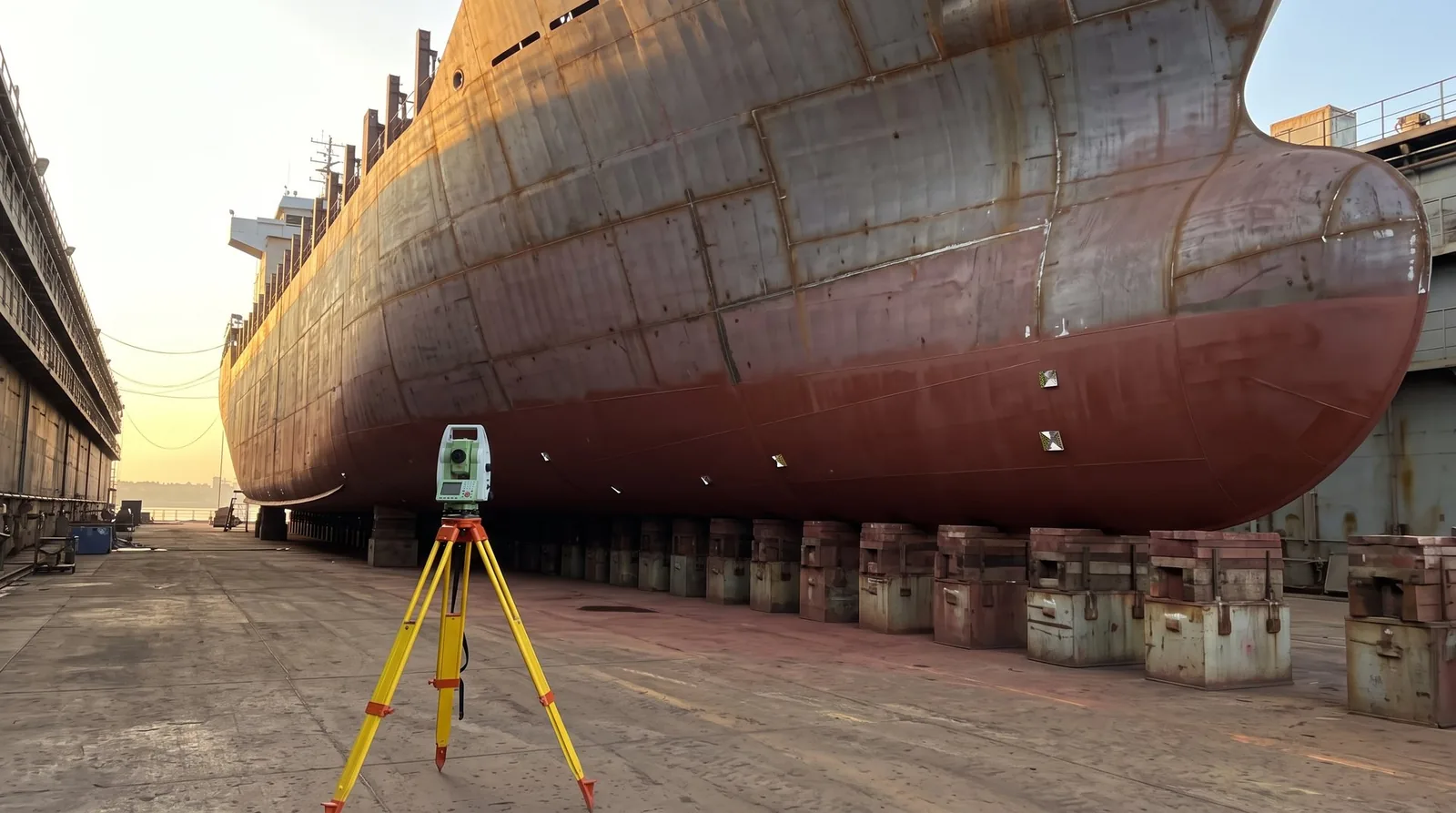
Keel sighting and deflection surveys explained: reference line, raw vs relative readings, thermal effects, weld shrinkage, IACS Rec. 47 and schedule impact.
How shipyards establish the keel reference line, measure hogging and sagging during construction, separate bending from settlement and temperature effects, and connect welding sequence, class quality standards and the schedule. With worked numbers on a hypothetical 150 m hull.
Dimensional accuracy is a basic requirement of hull construction. The alignment of structural members, the fit of blocks at erection and the control of welding-induced deformation all feed into later work: closing joints, fitting machinery foundations and aligning the shaft line.
Keel sighting and keel deflection surveys are two related dimensional control activities that monitor the longitudinal geometry of the hull while it is being built. The terms are sometimes used interchangeably in shipyards, but they serve different purposes.
Keel sighting establishes and checks the longitudinal reference line of the vessel. The term is not informal shorthand: IACS Recommendation No. 47, the quality standard that IACS UR Z23 names as the default for hull construction, states its whole-length deformation criterion "against the line of keel sighting".
Keel deflection surveying measures how the longitudinal profile of the hull changes during construction. Those changes can come from structural weight, welding shrinkage, temporary support conditions, block erection and temperature.
Together, the two activities give production, quality control and engineering the dimensional information they need to identify deviations, investigate their causes and decide whether anything has to be done.
Dimensional control is not a matter of keeping the keel perfectly straight. A steel hull deforms elastically, and its measured shape depends on how it is supported, how it is loaded and how warm its different parts are at the moment of measurement. The objective is to keep the geometry within the design, construction and classification requirements that apply to the particular vessel.
This article covers the principles of keel sighting, the practical execution of deflection surveys, the link between welding sequence and hull deformation, and what dimensional deviations can mean for cost and schedule. Four worked scenarios on a hypothetical 150 m hull show the arithmetic behind the interpretation. The numbers in those scenarios are illustrative. They are not measured data, not predictions for a real hull and not recommended values.
Understanding Keel Sighting and Hull Alignment
The purpose of keel sighting
The keel is a principal longitudinal member of a conventional ship. Together with the bottom shell, longitudinal girders, floors and the rest of the bottom structure, it contributes to the longitudinal strength of the hull girder. During construction, the keel and other designated reference points give the yard a physical basis for checking the vessel's longitudinal geometry.
Keel sighting establishes or verifies that reference geometry. Depending on the design and the construction method, the survey may cover:
- the longitudinal alignment of designated keel reference points;
- the relative heights of selected points along the hull;
- the alignment of structural components against the approved construction drawings;
- the geometric relationship between the hull and critical references such as machinery foundations.
The exact scope depends on the vessel, the construction stage and the inspection requirements agreed for the project.
A keel sighting survey should not be confused with a full hull dimensional inspection. It focuses on a defined reference line or set of points. A comprehensive dimensional survey also covers transverse alignment, block geometry, deck heights, bulkhead positions and local structural tolerances.
Establishing the construction reference
Before any measurement can be evaluated, the yard needs a reliable geometric reference. The reference system is set up from the approved design information and the yard's construction datum. Surveyors must understand how the design baseline, the construction baseline and the physical reference points on the building berth or in the dock relate to one another.
The initial survey should record:
- the design centreline and baseline of the vessel;
- the coordinates and heights of the designated survey points;
- the position, height and condition of the keel blocks and any other supports;
- the construction stage and the structural loading condition;
- the measuring instrument and its calibration status.
The keel blocks are particularly important at this stage, because their positions and heights define the initial support condition of the hull. Uneven block heights, local settlement or a poor distribution of supports can introduce deformation before major erection begins. The initial survey should therefore document the actual support arrangement rather than assume the hull starts in an ideal, undeformed state.
Survey datums and reference points
A survey datum is the reference from which dimensional measurements are taken. Choosing a datum and keeping it unchanged is what makes measurements from different construction stages comparable.
Survey points should be clearly marked and reproducible. Each point should be recorded with its frame number, longitudinal position or drawing coordinate, the type of mark and preferably a photograph, so that a different surveyor can find exactly the same point months later.
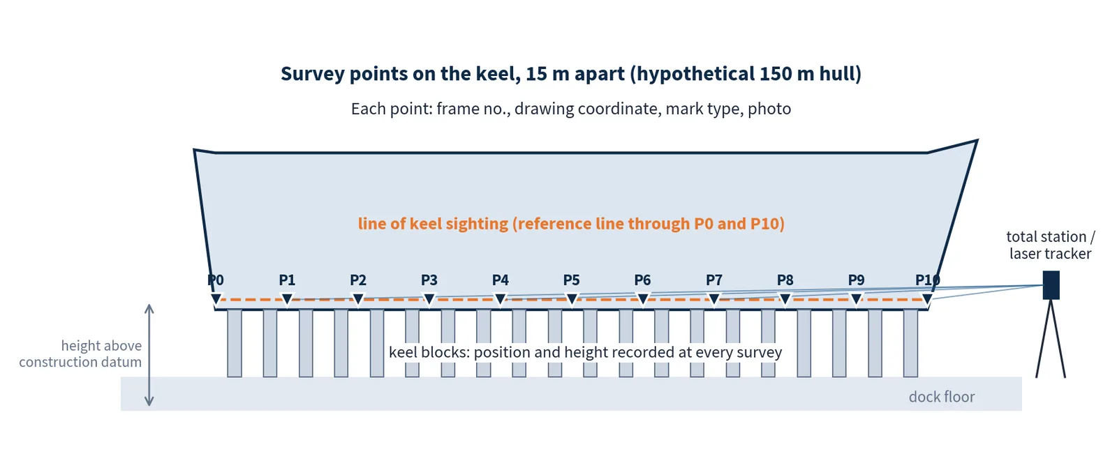
Where measurements are repeated over weeks or months, the team should use the same points and a documented method. If the datum, the instrument set-up or the identification of a point changes, the new results may not be directly comparable with the old ones, and the change must be stated in the survey record.
Keel Deflection Survey: Principles and Methodology
What is keel deflection?
Keel deflection is a change in the longitudinal profile of the keel or of another designated reference line on the hull.
In a simplified longitudinal model, the hull behaves like a long beam resting on keel blocks or other construction supports. Its profile changes as the structure is assembled, loaded and welded. Two terms describe longitudinal bending:
- Hogging: the middle of the hull is higher than the bow and stern, measured against the reference line.
- Sagging: the middle of the hull is lower than the bow and stern, measured against the same line.
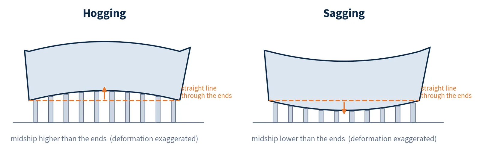
These terms describe a shape. They are not, on their own, evidence of a structural defect. A hull under construction can show measurable elastic deformation under normal conditions. What matters is the size of a deviation, its distribution along the hull, its trend over successive surveys and its effect on the work that follows.
Factors affecting hull deflection
Several factors act at the same time.
Structural weight and loading. As construction progresses, the weight of added blocks, machinery, outfit items and temporary equipment changes the load distribution along the hull. The position of heavy items is particularly relevant when they are installed before the hull is fully supported or before the structure has reached its intended stiffness.
Keel block arrangement. The number, position and height of the blocks determine how the hull is supported. Local settlement, uneven contact or a change in the support arrangement can alter the measured profile.
Welding shrinkage. Welding heats the steel locally, and the weld and the surrounding metal contract as they cool. The resulting shrinkage produces longitudinal, transverse and angular distortion. When welding is concentrated in one area, or carried out in an unbalanced sequence, the cumulative effect can change the geometry of a larger assembly.
Temperature. Steel expands when heated and contracts when cooled. Direct sunlight, a temperature difference between the upper and lower parts of the hull, and a difference between port and starboard can all affect measured dimensions. For this reason, relevant environmental and structural temperatures should be recorded with every survey, particularly when comparing measurements taken at different times of day.
Construction sequence. The stiffness of the hull changes as blocks, decks, bulkheads and longitudinals are added. A measurement taken just after keel laying does not necessarily represent how the structure behaves after the main erection or after extensive welding.
Scenario B: an idealised thermal calculation
This scenario is an order-of-magnitude illustration based on an idealised free-beam model. It is not a prediction of how a real hull supported on keel blocks will deform.
Assume a free beam whose top is warmer than its bottom, with the temperature varying linearly through the depth and uniformly along the length. Such a beam bends with a constant curvature κ = αΔT / D, where α is the coefficient of thermal expansion, ΔT the top-to-bottom temperature difference and D the depth. Over a span L, constant curvature gives a midspan rise, relative to the line through the ends, of
δ = κL² / 8 = αΔT·L² / (8D)
For structural steel, EN 1993-1-1 gives α = 12 × 10⁻⁶ per °C. For a free beam with L = 150 m:
| Top-to-bottom ΔT | Midspan rise, D = 10 m | D = 14 m | D = 20 m |
|---|---|---|---|
| 5 °C | 16.9 mm | 12.1 mm | 8.4 mm |
| 10 °C | 33.8 mm | 24.1 mm | 16.9 mm |
| 15 °C | 50.6 mm | 36.2 mm | 25.3 mm |
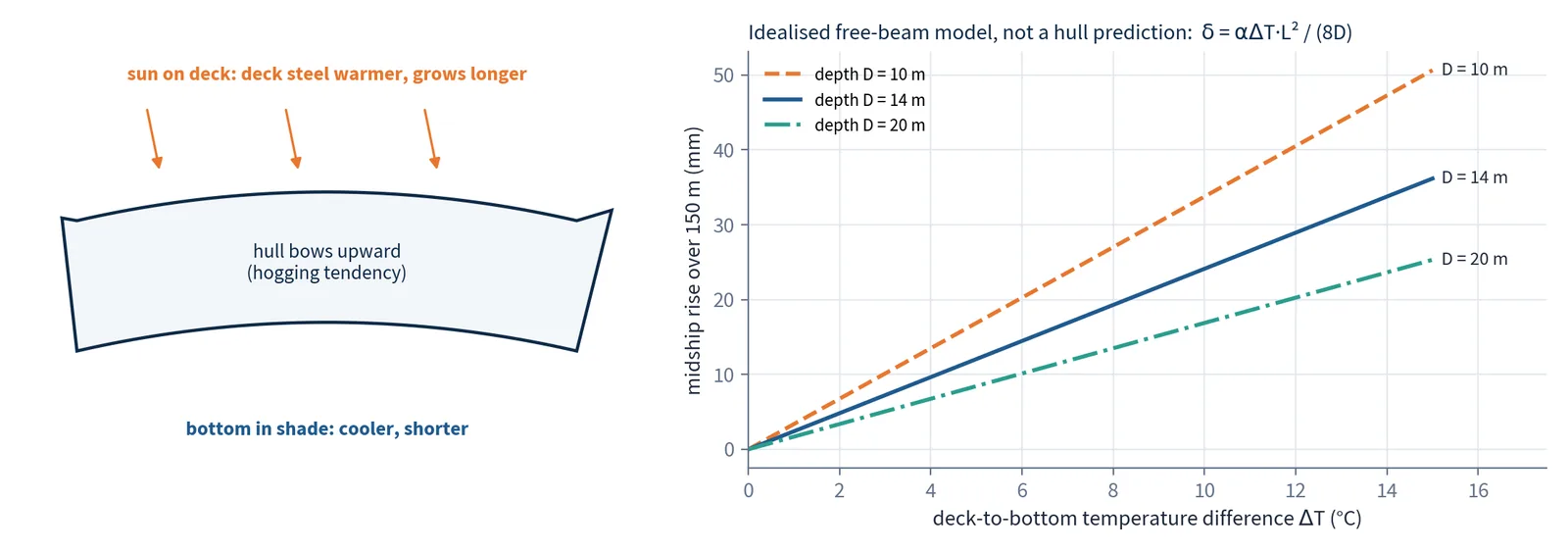
A real hull differs from this model in every assumption. It rests on keel blocks and is held down by its own weight, so support reactions redistribute as it tries to bend. Its temperature distribution is not linear through the depth and not uniform along the length, and it changes through the day. Its stiffness varies along the length and with the construction stage. The actual response can therefore be considerably smaller than the table suggests, or differently shaped, and it cannot be known without measurement.
What the calculation does show is sensitivity: in steel of this length, a temperature difference of a few degrees between the upper and lower structure is enough, in principle, to produce profile changes of the same order as the effects a survey is trying to detect. For reference, a uniform change of 10 °C alters the length of 150 m of steel by about 18 mm (150,000 mm × 12 × 10⁻⁶ × 10).
Temperature control is recognised in class guidance for a closely related activity. The ABS Guidance Notes on Propulsion Shafting Alignment state, for sighting through the shaft line, that "the temperature of the vessel's structure must be stable and as even as possible" and that "for that reason, boresighting is normally conducted in early morning hours before the sunrise". That recommendation concerns shaft-line sighting, not keel deflection surveys. For keel surveys, the time of measurement and the thermal conditions to record should be defined in the project's measurement procedure, so that successive surveys are taken under comparable, documented conditions.
Measurement equipment
Several instruments can be used to establish and monitor hull geometry.
Total station. Measures horizontal and vertical angles and distances to targets, giving coordinates and heights of the survey points. Its suitability depends on the required accuracy, the survey geometry, the set-up and the environmental conditions.
Theodolite. Measures horizontal and vertical angles. It can be used for alignment surveys when suitable reference points and procedures are in place. A conventional theodolite does not measure distance directly.
Laser tracker. Provides highly accurate three-dimensional measurements over suitable working distances. It may be used for precision inspection of large assemblies and selected critical components, subject to line of sight, range and the required uncertainty.
Traditional methods. Piano wires, optical alignment instruments and water levels have also been used for alignment and height measurements. The ABS shafting guidance, for example, names optical instruments, lasers and piano wire as means of sighting through a shaft line. These methods may remain useful for particular applications, provided their limitations and uncertainty are understood.
Measurement uncertainty should be estimated for the actual set-up rather than taken from the instrument grade alone. As a simple illustration, an angular uncertainty of 2 arc-seconds corresponds to about 0.7 mm of height at 75 m (75,000 mm × 2 / 206,265) and about 1.5 mm at 150 m. Target set-up, point identification, refraction and the stability of the instrument station add to this. Field procedures for checking the precision of theodolites and total stations are standardised in ISO 17123-3 and ISO 17123-5. The use of modern equipment alone does not guarantee reliable results.
Survey preparation
Before a deflection survey, the team should prepare a measurement plan that defines:
- the reference datum and the survey points;
- the instrument and the measurement method;
- the required measurement accuracy;
- the construction stage at which the survey is taken;
- the loading and support condition of the hull;
- the environmental and structural temperatures to record, and the time of day at which the survey is taken;
- how deviations will be evaluated and reported.
The team should also confirm that the points are accessible, identifiable and suitable for repeated measurement. Where possible, each survey should be taken under conditions comparable to the previous one. Where that is not possible, the differences should be recorded and taken into account in the evaluation.
Survey frequency and construction milestones
Survey frequency should be determined by the construction plan, the structural characteristics of the vessel and the quality requirements. A practical programme may include surveys:
- after the keel blocks are set and the construction reference is established;
- after keel laying or the first bottom blocks are landed;
- after the erection of major blocks;
- after welding operations that may affect the longitudinal geometry;
- before and after the installation of major machinery or heavy equipment, where relevant;
- before critical alignment activities and major construction milestones;
- after any unexpected structural movement or suspected support settlement.
Not every project requires a survey after every block or every welding operation. The frequency should be proportionate to the risk and to the expected effect of the work.
The ABS shafting guidance is relevant to the survey before shaft line work. For sighting through, it asks that major welding on the stern block be completed and that heavy structural parts and equipment, such as the superstructure and main engine, be installed before the reference line is established. It also expects the alignment established in the dock to be disturbed by hull girder deflection once the vessel is afloat, and states that final alignment should be verified in the afloat condition. Where a project needs to know how the hull moves between the docked and afloat conditions, surveys before and after float-out can provide that information.
Interpreting Hogging and Sagging During Construction
Understanding the measured profile
A deflection survey gives the geometry of the hull at selected points. Those readings must be interpreted against the agreed reference profile. A useful first step is to separate three kinds of change that all appear in raw heights:
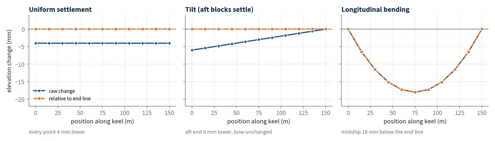
- Uniform settlement: every point moves by the same amount. The hull, or the datum, has moved as a whole; the shape has not changed.
- Tilt: heights change linearly along the length, for example because the aft supports have settled more than the forward ones. The hull has rotated as a rigid body; the shape has not changed.
- Bending: the middle moves relative to the ends. Only this is a change in longitudinal profile.
Subtracting a straight reference line removes the first two and leaves the third. In the scenarios below, the reference line is the straight line through the two end survey points.
Scenario A: three surveys on the hypothetical hull
The hypothetical hull is surveyed three times at the eleven points of Figure 1. Survey 1, after block setup, is the reference, so all its changes are zero by definition. The values below are constructed from exact components so that every figure can be checked by hand:
- Survey 2 (after erection of the major blocks): 4 mm uniform settlement, plus an aft tilt of 6 mm at P0 decreasing linearly to 0 at P10, plus a bending component of 18 mm sag at midship.
- Survey 3 (after welding of the upper deck erection butts): the same settlement and tilt as Survey 2, with no further support movement, plus a bending component of 33 mm sag at midship.
All values are changes in height from Survey 1, in millimetres. "Bending" is the value relative to the straight line through P0 and P10.
| Point | Position (m) | Settlement | Tilt | Bending S2 | Raw S2 | Bending S3 | Raw S3 |
|---|---|---|---|---|---|---|---|
| P0 | 0 | −4.0 | −6.0 | 0.0 | −10.0 | 0.0 | −10.0 |
| P1 | 15 | −4.0 | −5.4 | −6.5 | −15.9 | −11.9 | −21.3 |
| P2 | 30 | −4.0 | −4.8 | −11.5 | −20.3 | −21.1 | −29.9 |
| P3 | 45 | −4.0 | −4.2 | −15.1 | −23.3 | −27.7 | −35.9 |
| P4 | 60 | −4.0 | −3.6 | −17.3 | −24.9 | −31.7 | −39.3 |
| P5 | 75 | −4.0 | −3.0 | −18.0 | −25.0 | −33.0 | −40.0 |
| P6 | 90 | −4.0 | −2.4 | −17.3 | −23.7 | −31.7 | −38.1 |
| P7 | 105 | −4.0 | −1.8 | −15.1 | −20.9 | −27.7 | −33.5 |
| P8 | 120 | −4.0 | −1.2 | −11.5 | −16.7 | −21.1 | −26.3 |
| P9 | 135 | −4.0 | −0.6 | −6.5 | −11.1 | −11.9 | −16.5 |
| P10 | 150 | −4.0 | 0.0 | 0.0 | −4.0 | 0.0 | −4.0 |
Each raw value is the sum of the three components to its left (for example, P4 in Survey 3: −4.0 − 3.6 − 31.7 = −39.3). Real survey readings would also contain measurement scatter; it is left out here to keep the arithmetic traceable.
Three observations follow.
- The raw midship reading in Survey 2 is 25 mm below Survey 1, but only 18 mm of that is bending. The other 7 mm (4 mm settlement and 3 mm of tilt at midship) describes the supports, not the shape of the hull. Reporting 25 mm as "sag" would overstate the bending by almost 40 %.
- Between Surveys 2 and 3 the bending at midship grows by 15 mm, from −18.0 mm to −33.0 mm, while the supports have not moved. The trend between comparable surveys is the finding, not any single value.
- A local check can behave very differently from the whole-length check. If bulkheads stand at P3 and P5 (30 m apart), the deviation of P4 from the straight line between them in Survey 3 is −31.7 − (−27.7 − 33.0) / 2 ≈ −1.3 mm. A smooth overall sag produces little local deviation; a large local value would point to a local effect at a joint rather than to overall bending.
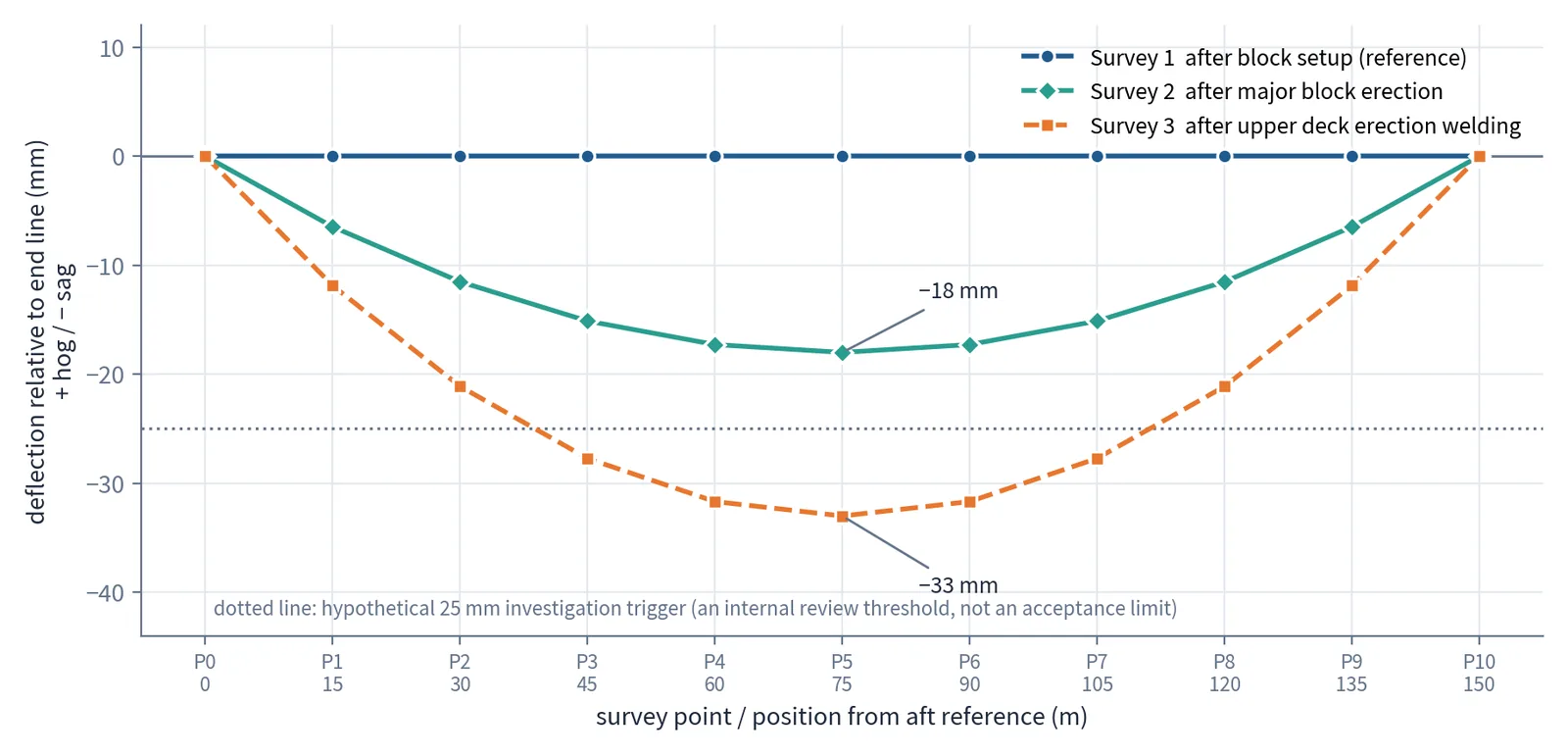
Whether the Survey 3 profile is acceptable depends on the criterion agreed for the project, discussed in the section on classification requirements below. Independently of acceptance, a yard would want to understand why the hull profile changed by 15 mm between two surveys, because further work may continue the trend and later alignment work will be carried out on this hull. A project may therefore choose to define, in its dimensional control procedure, an internal investigation trigger that is set below the acceptance criterion. In this hypothetical project that trigger is 25 mm of relative deflection, so Survey 3 triggers a review. The practical example near the end of the article follows that review.
Limitations of an end-point reference line
A straight line through the two end points is simple and transparent, but it has limitations that the survey procedure should address.
- Every error at an end point is spread along the hull. If one end reading is wrong by e, every relative value changes in proportion to its distance from the other end, and the midship value changes by e / 2. In Scenario A, a 3 mm error at P10 would change the midship result by 1.5 mm.
- The end points must themselves be stable. If an end point sits on structure that deforms locally, for example an overhanging end block or an area that is still being welded, local movement there is reported as a change in the whole profile. End points should be placed on stiff, well-supported structure and re-observed at every survey.
- The end points need not coincide with the design reference. Some Rec. 47 shape items, such as cocking-up of the fore body and rise of floor amidships, are measured from the design line rather than from an end-point line. The reference used for each check should be stated.
- Alternatives exist. A best-fit line through all points, or comparison with the design line, gives different numbers from the same readings. Whatever method is chosen should be defined in the procedure, agreed where relevant with the classification society, and used consistently across all surveys.
Hogging: possible causes and implications
Hogging means the middle of the hull is higher than the ends relative to the reference line. During construction, possible contributing factors include:
- uneven support conditions;
- changes in structural loading;
- welding shrinkage and the distribution of welded joints;
- temperature differences along and through the hull;
- changes in the structural stiffness of the assembled hull.
The direction of deflection alone does not identify the cause. A hogging reading taken while the upper structure is warmer than the bottom may partly reflect a thermal gradient (see Scenario B). A survey that indicates increasing hogging under comparable conditions should trigger an engineering review of the measurement results and of the construction activity since the previous survey.
Sagging: possible causes and implications
Sagging means the middle is lower than the ends. Possible contributing factors include:
- concentrated structural or equipment loads;
- uneven support reactions;
- local settlement of supporting structures;
- welding-induced shrinkage;
- changes in the stiffness and load distribution of the hull.
A sagging trend should be assessed together with the construction stage and the support arrangement. If heavy machinery or other major components have recently been installed, their weight and location may be relevant to the investigation. It is equally important not to attribute every sagging condition to machinery weight. The survey results must be evaluated alongside the actual structural and support conditions.
Temporary deformation versus persistent deviation
One of the central tasks in dimensional control is deciding whether a measured deviation is temporary or persistent. A hull deforms elastically as loads are added or removed, and temperature changes produce reversible dimensional variations. A deviation observed in one survey may therefore not represent the final geometry of the completed structure.
Repeated measurements under documented conditions help the engineering team identify trends and distinguish temporary variation from persistent change. Where necessary, additional measurements after a change in loading or support conditions show how the hull responds.
Rec. 47 adds a process point that applies directly to survey data. Its scope section states that fit-ups, deflections and similar quality attributes are intended to be uniformly distributed about the nominal values, that the shipyard is to take corrective action to improve work processes where a skewed distribution is evident, and that relying on remedial steps that truncate a skewed distribution is unacceptable. Applied to dimensional surveys, a persistent drift in one direction is a signal to review the process (sequence, fit-up, supports), not only to correct individual results.
Welding Distortion and Its Effect on Hull Geometry
How welding causes distortion
Welding involves localised heating of the joint edges, followed by cooling and contraction. As TWI explains in its guidance on distortion, the heated metal expands but is restrained by the cooler surrounding material, so compressive stresses develop. On cooling, the weld metal and the heat-affected zone contract; that contraction is also restrained, and tensile stresses develop. Where these stresses exceed the yield strength of the metal, plastic deformation takes place and the dimensions change permanently.
Hull structures contain long seams, large plates, stiffeners and complex assemblies, so the effects can be significant. TWI distinguishes six forms:
- Longitudinal shrinkage: shortening along the weld.
- Transverse shrinkage: contraction across the weld.
- Angular distortion: rotation of plates or members caused by uneven contraction through the thickness of the joint.
- Bowing: curvature of a member along its length when the weld lies away from the neutral axis.
- Buckling: loss of stability of thin plate under compressive stress.
- Twisting: rotation of box and open sections about their length.
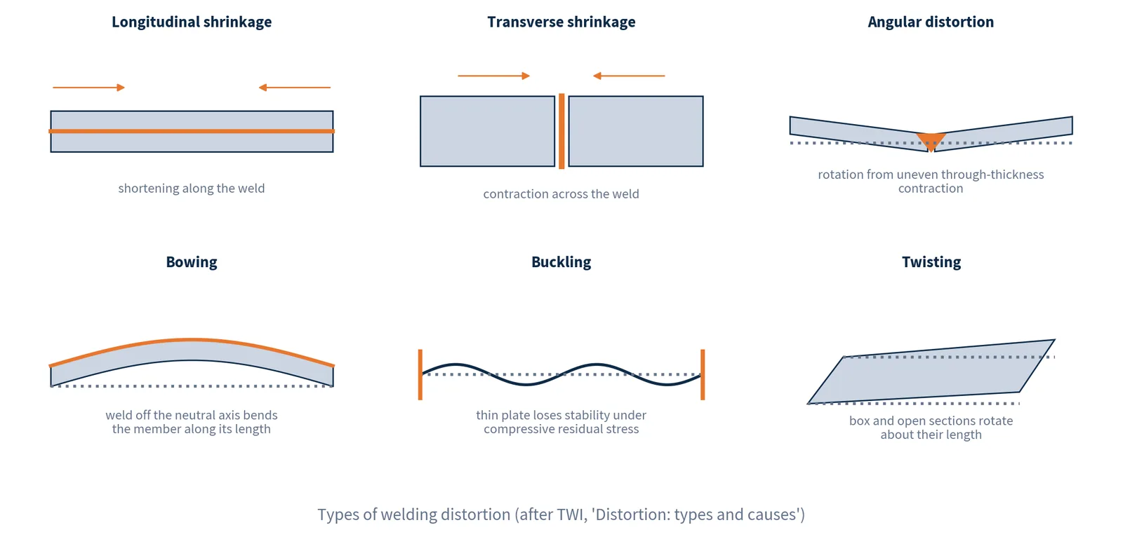
These mechanisms act on individual panels and blocks and, when their effects accumulate, can affect the overall geometry of the hull.
Factors influencing welding distortion
Parent material. Thermal expansion drives distortion. TWI notes, for example, that stainless steel, with a higher coefficient of expansion than plain carbon steel, is more likely to distort.
Deposition and number of runs. TWI's fabrication guidance recommends depositing the weld metal as quickly as possible and using the least number of runs needed to fill the joint. The relationship between heat input and distortion is not always straightforward: joint geometry, process and restraint also affect the outcome.
Weld size and weld volume. More weld metal means more contracting material. Weld sizes should comply with the approved design and welding procedure. Over-welding should not be used as a substitute for correct joint preparation and fit-up.
Joint design and preparation. Root gap, bevel angle and joint geometry determine how much weld metal is needed. TWI notes that double-sided joints balance the thermal stresses better than single-sided ones, and that uniform gaps give more consistent shrinkage. Poor fit-up may require additional weld metal or remedial work, potentially increasing distortion.
Welding sequence. The order in which joints are welded affects whether shrinkage balances out or accumulates in one direction.
Restraint. Clamps, strongbacks, jigs and temporary supports restrict movement during welding. TWI notes that restraint reduces movement but increases residual stress and the risk of cracking. The restraint method must be appropriate for the material, the joint and the welding procedure.
From joint shrinkage to hull bending
A single erection butt shrinks by a small amount. One way in which joint shrinkage can affect the hull profile is through a difference between the shrinkage at the upper and lower parts of the hull girder. If the deck side of an erection joint shrinks more than the bottom side, the geometry of the joint implies a small relative rotation between the adjacent blocks, approximately
θ = Δ / D
where Δ is the difference between deck and bottom shrinkage at the joint and D the depth of the hull.
Scenario C: an illustrative geometric calculation
This scenario is a geometric illustration with assumed shrinkage values. It is not measured shipyard data and it is not a validated prediction of hull deformation.
Treat the hypothetical hull as ten rigid blocks of 15 m joined at nine erection joints, depth D = 14 m, free to rotate at the joints:
- Case C1 (assumed): every joint has 0.5 mm more shrinkage at the deck than at the bottom. Each joint rotates by 0.5 / 14,000 ≈ 36 microradians. Summed along the hull, the geometry gives a sag of 6.7 mm at midship relative to the end line.
- Case C2 (assumed): only the three midship joints are affected, with a 1.0 mm difference each. The geometry gives a sag of 7.0 mm, concentrated at the middle joints.
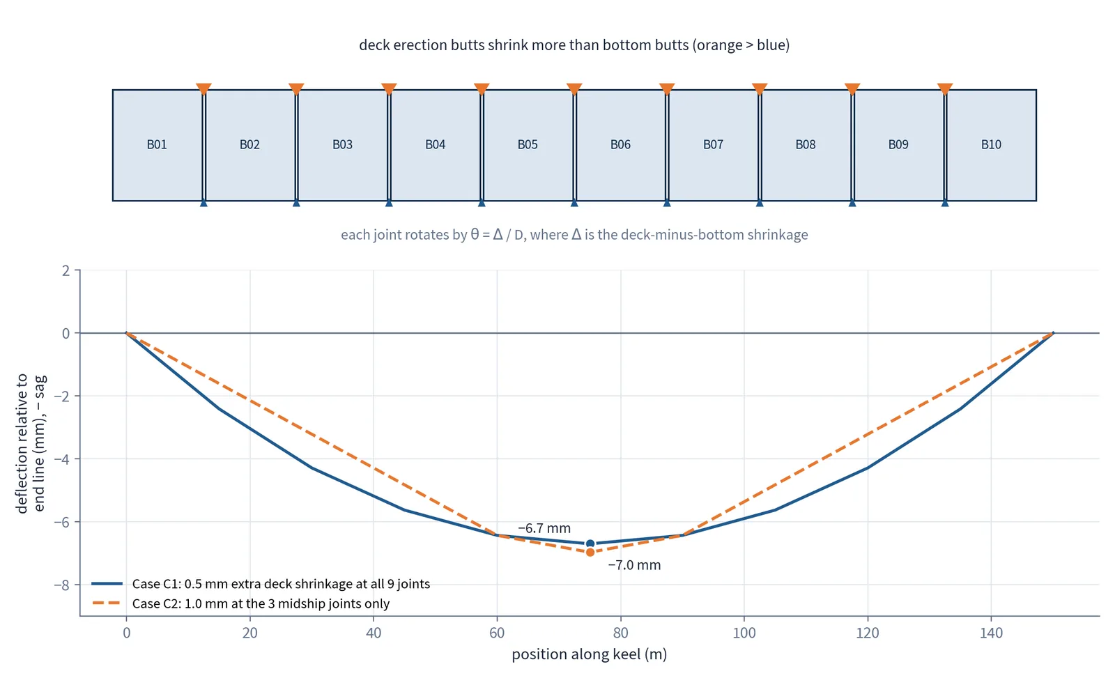
The calculation shows that a fraction of a millimetre per joint, accumulated along the length, is geometrically capable of producing a measurable change in profile. It does not show what a real hull will do. The actual effect depends on:
- the stiffness of the hull girder and of each block, which the rigid-block model ignores;
- the restraint provided by the keel blocks, the self-weight of the structure and any temporary supports;
- the joint configuration, plate thicknesses and welding procedure;
- the actual distribution of shrinkage through the depth and along the length, including side shell, longitudinal bulkheads and internal structure, not only deck and bottom;
- the sequence in which the joints and adjacent seams are welded.
Shrinkage values for a real vessel should come from the yard's own documented measurements for comparable joints. The calculation is best used as a sense check of orders of magnitude, not as a means of attributing a measured deflection to a particular welding activity.
Welding Sequence Optimization for Distortion Control
The purpose of welding sequence planning
Welding sequence planning is the arrangement of welding operations to achieve the required structural quality while controlling deformation and maintaining production efficiency. In shipbuilding it applies at several levels:
- individual welded joints;
- plate panels and stiffened assemblies;
- sub-blocks and blocks;
- major hull blocks during erection;
- the overall construction sequence.
A method that is effective for a small plate panel may not be appropriate for a large hull block. The techniques described below are options to be selected according to the joint, the structural configuration, access, the approved welding procedure and the production resources. None of them is a universal rule.
Balanced welding
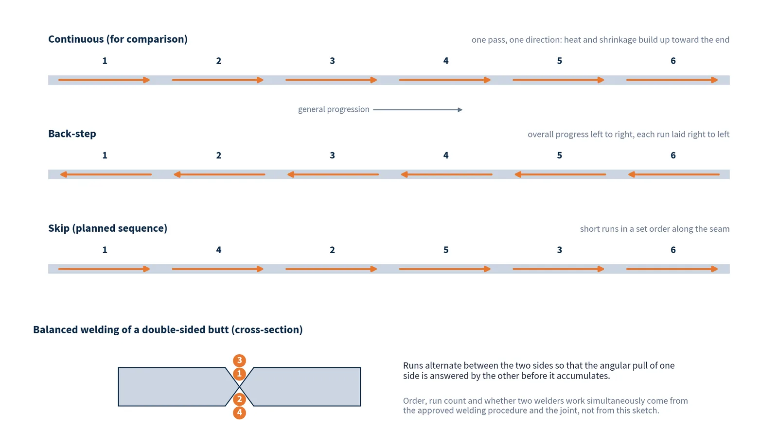
Balanced welding is intended to reduce the accumulation of angular distortion by distributing weld metal on opposite sides of a joint or around the neutral axis of a section. TWI describes two ways of achieving it on double-sided joints: two welders working simultaneously on opposite sides, or a planned alternation of runs between the sides.
In large structures, balanced welding may involve coordinating work between different locations or welders. Simultaneous welding is not always practical or necessary. The approach should be selected according to the approved welding procedure, access limitations and structural configuration.
Back-step welding
Back-step welding is a technique in which short weld runs are deposited in the direction opposite to the general progression of the seam. For example, the seam as a whole may progress from left to right, while each individual run is deposited from right to left. TWI lists back-step welding among the techniques that use short runs to control distortion. It is not a universal solution for all shipyard joints; its suitability depends on the joint geometry, welding process, access and production requirements.
Skip welding
Skip welding involves depositing short runs at intervals along the seam in a planned order, rather than completing a long seam continuously. TWI describes the runs as evenly spaced along the seam. Distributing the heat in this way can reduce its concentration in one area and may help limit distortion. Segment lengths, spacing and order should be defined for the joint and the welding procedure rather than taken as a fixed value for every application.
Center-outward welding
Center-outward welding is sometimes used for large panels and assemblies to help distribute shrinkage and reduce the accumulation of distortion. It should not be treated as a rule requiring every ship structure to be welded from the centre toward the ends.
TWI's general guidance is that the welding sequence should progress toward the free end of the joint, while taking care that the whole of the weld is not completed in one direction. For a panel that is symmetrical and restrained around its edges, working from the centre outward is consistent with that guidance. For an assembly restrained at one end, welding from the restrained area toward the free end may be more appropriate. In other cases a symmetrical sequence may be preferred.
The engineering objective is controlled and predictable shrinkage while maintaining the required weld quality.
Controlling welding distortion at block level
At block level, distortion control requires coordination between fabrication and dimensional control teams.
Before welding begins, the production team should verify the block's alignment, joint preparation, fit-up and temporary restraint arrangement. During welding, the planned sequence should be followed, and significant deviations should be recorded. After welding, the block should be inspected to verify that its dimensions remain within the applicable requirements. Where a block shows significant distortion, additional measurements may be required before it is released for subsequent assembly or erection, and the results should be available to the team responsible for the next construction stage.
Rec. 47 gives block assembly criteria that show the scale involved. For a flat plate assembly, for example, it lists a "standard" of ±4 mm and a "limit" of ±6 mm for length and breadth, ±10 mm and ±20 mm for distortion, and ±5 mm and ±10 mm for squareness. These values apply only where Rec. 47 is the agreed standard for the project, and only to the items it names.
When distortion has to be corrected
Where a block or panel is outside its criteria, correction may be mechanical (for example pressing) or thermal (line, spot or wedge-shaped heating). TWI notes that thermal correction works by locally heating the material so that the hot, lower-yield-strength metal is plastically deformed as it tries to expand against the surrounding cold metal, and that mechanical straightening requires slight over-correction to allow for elastic spring-back.
Heating limits are material-specific. Rec. 47 Table 6.5 gives maximum surface temperatures for line heating of hull steels, for example under 650 °C for conventional-process AH32 to EH36 steel with water cooling immediately after heating, with different values for TMCP steels depending on carbon equivalent and cooling method. Any correction method must be suitable for the material and must be carried out and inspected under the yard's approved procedures and, where required, with the agreement of the classification society.
Using Survey Results to Manage Welding and Structural Deformation
Establishing a measurement-based control process
Keel deflection measurements are most useful when they are integrated into the shipyard's dimensional control process rather than treated as isolated inspections. A workable process has five stages:
- Establish the reference geometry and record the initial measurements.
- Repeat the measurements at defined construction milestones.
- Compare the results with previous measurements and with the applicable criteria.
- Verify the measurement, then investigate significant deviations or unexpected trends.
- Agree corrective or preventive measures and verify their effect with a follow-up survey.
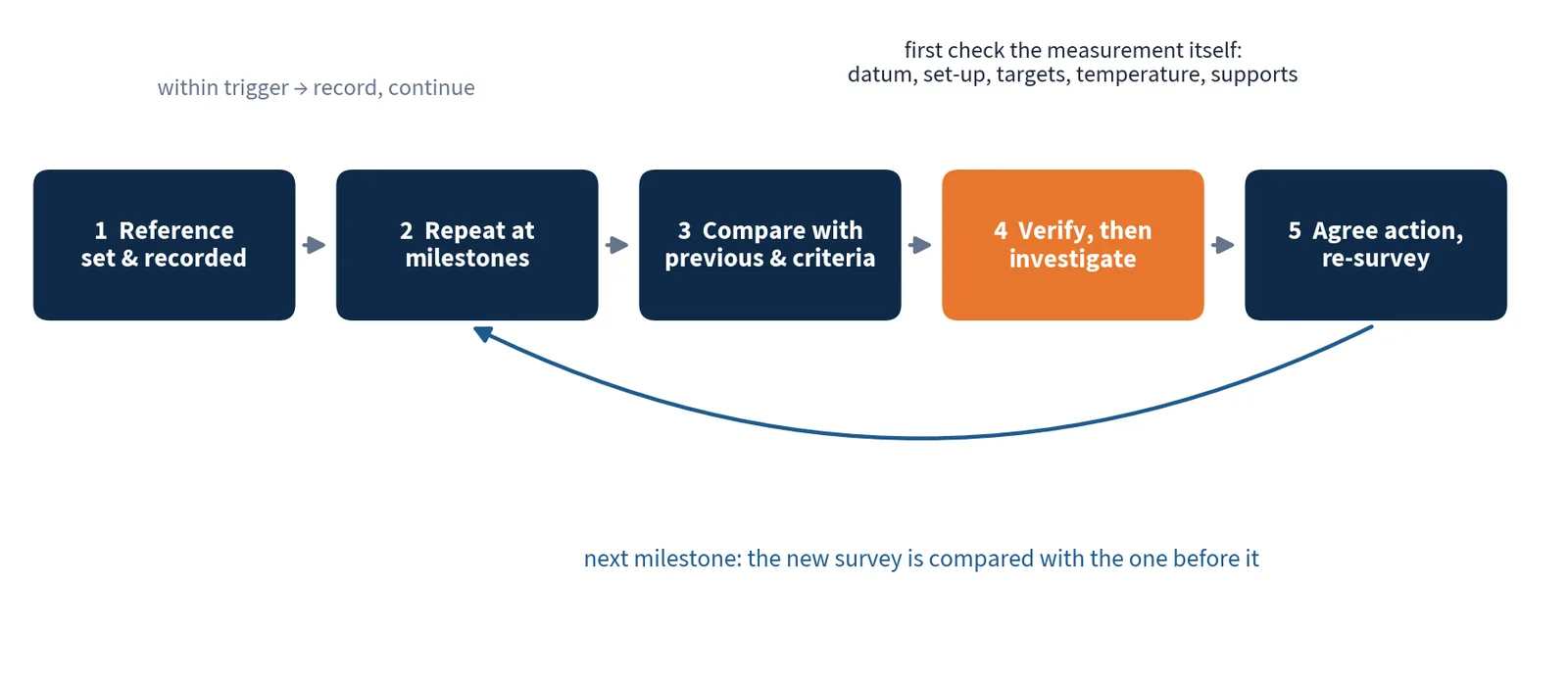
The survey team provides reliable measurement data. The responsible engineering and production teams evaluate the results and determine the appropriate actions.
Responding to a hogging or sagging trend
When measurements indicate an increasing hogging or sagging trend, the first step is to verify the measurement results. The team should check the survey datum, the instrument set-up, the target locations, the environmental conditions and the support and loading state of the hull.
If the trend is confirmed, the engineering team should review the construction activities that may have contributed. Depending on the findings, possible actions include:
- reviewing the planned welding sequence;
- revising the sequence of welding still to be done;
- reviewing the distribution of temporary loads;
- inspecting keel blocks and other supports;
- checking the alignment and fit-up of affected structures;
- conducting additional surveys to monitor the response.
Revising the sequence of the remaining welds may influence further distortion. It should not be relied on to reverse a deflection that is already present, and it should not be assumed that additional welding in a particular region will correct a measured deflection. Any corrective welding operation must be assessed for its effects on residual stress, weld quality and dimensional accuracy.
Verifying corrective actions
Following a corrective action, a follow-up survey should be performed under documented conditions and compared with the survey before the intervention. The comparison helps determine whether the action produced the intended dimensional response. If the deviation remains or increases, the engineering team may need to reassess the original diagnosis and consider other measures.
The objective is not simply an acceptable reading at one point in time, but control of the hull's geometry throughout the relevant construction stages.
Classification Requirements and Dimensional Tolerances
Dimensional results are assessed against the requirements that apply to the particular project. These may include:
- the approved construction drawings;
- the yard's dimensional control procedures;
- the applicable classification society rules;
- a recognised shipbuilding quality standard;
- equipment manufacturers' alignment and installation requirements;
- project-specific technical specifications.
IACS Unified Requirement Z23, Hull Survey for New Construction, requires the shipbuilding quality standards for the hull structure to be reviewed and agreed at the kick-off meeting. Structural fabrication is to be carried out in accordance with IACS Recommendation No. 47, Shipbuilding and Repair Quality Standard, or a Recognized Fabrication Standard (RFS) accepted by the classification society before fabrication starts. Z23's table of surveyable items includes checking alignment and deformations during sub-assembly, block, grand and mega block assembly, pre-erection and erection, by patrol of the process and witness of the completed item.
Rec. 47 contains criteria for the shape of the hull. Tables 6.8 and 6.9 include:
| Item | Standard | Limit | Remarks |
|---|---|---|---|
| Deformation for the whole length | ±50 mm | not specified | per 100 m, against the line of keel sighting |
| Deformation for the distance between two adjacent bulkheads | ±15 mm | not specified | |
| Cocking-up of fore body | ±30 mm | not specified | measured from the design line |
| Cocking-up of aft body | ±20 mm | not specified | |
| Rise of floor amidships | ±15 mm | not specified | measured from the design line |
| Length between perpendiculars | ±L/1000 | not specified | ships of 100 m length and above |
| Moulded breadth at midship | ±B/1000 | not specified | ships of 15 m breadth and above, measured on the upper deck |
| Moulded depth at midship | ±D/1000 | not specified | ships of 10 m depth and above, measured up to the upper deck |
Source: IACS Rec. 47, Rev. 10 Corr. 1 (October 2025), Tables 6.8 and 6.9.
Several qualifications apply before these values are used:
- Standard and limit. Rec. 47 defines the "standard" range as the target range expected in regular work under normal circumstances, and the "limit" range as the maximum allowable deviation from the standard range. The items above give a standard value only. Where no limit value is specified, Rec. 47 states that a value beyond the standard range may be accepted subject to the consideration of the classification society. A standard value is therefore not the same as an acceptance limit.
- Interpretation of "per 100 m". The whole-length criterion is expressed per 100 m. A pro-rata reading would give ±75 mm for a 150 m hull, but that figure is not an unconditional acceptance limit: how the criterion is applied (over the full length or over a defined span, at which construction stage, and against which reference line) must be agreed with the classification society and set out in the project requirements.
- Scope. Rec. 47 is intended to provide guidance where established and recognised shipbuilding or national standards accepted by the classification society do not exist. It generally applies to conventional merchant ship types in normal and higher strength hull structural steel, its applicability is to be agreed with the classification society in each case, and it does not generally apply to special types such as gas tankers or to stainless steel structures. A more stringent standard may be required for critical and highly stressed areas.
- Other requirements. Rec. 47 notes, for items such as the main engine bed, that dimensions and tolerances have to fulfil engine and equipment manufacturers' requirements, if any. Hull shape criteria do not replace those requirements.
A deviation that is acceptable for one structural component may not be acceptable for a machinery foundation or another critical installation. The survey report should therefore identify the applicable acceptance criterion for each check and its source. Where a measured deviation exceeds the applicable limit, the shipyard should follow its established non-conformity and engineering review procedures. Any proposed repair or dimensional correction should be evaluated and accepted by the responsible parties, including the classification society where required.
Consequences of Poor Dimensional Control
Block fit-up and erection problems
Dimensional deviations in individual blocks can accumulate during hull erection. If the geometry of adjacent blocks does not match the approved assembly dimensions, the production team may encounter excessive gaps, misalignment or difficulty maintaining the required structural geometry. Such problems may require additional fit-up work, temporary restraint, local adjustment or approved remedial measures, and can increase the time required for block erection and final welding.
Machinery installation and shaft alignment
The alignment of the propulsion system is a critical installation activity. The main engine, gearbox where fitted, intermediate shaft, stern tube and propeller shaft must satisfy the applicable alignment requirements. The ABS shafting guidance identifies hull deflections and temperature change as the primary sources of disturbance to the established alignment, noting that hull deflections affect all bearings simultaneously while temperature effects may be local to a particular bearing or set of bearings.
Keel deflection alone does not establish whether the shaft line is correctly aligned. Shaft alignment is evaluated with its own procedure, which the ABS guidance describes as including sighting through, slope boring or bearing inclination, sag and gap, and bearing reaction measurements, taking into account the relevant structural, thermal and loading conditions. Keel deflection survey results can inform the planning of that work by showing how the hull geometry has changed. If significant dimensional deviations are not identified early, they may complicate machinery installation and require additional engineering or alignment work.
Welding rework and inspection
Excessive distortion may lead to additional cutting, straightening, fit-up adjustment or repair welding. These activities consume production resources and may require additional inspection. Where repairs affect welds or structural dimensions, the relevant inspection and non-destructive testing requirements must be followed. Unplanned rework may also disrupt the availability of work areas and interfere with other production activities.
Schedule and cost implications
Dimensional deviations can affect several interconnected construction activities. A block that requires additional alignment work may not be released for erection as planned, which can delay lifting operations, welding, outfitting or subsequent inspections. The impact depends on the criticality of the affected activity, the availability of alternative work and the possibility of performing other tasks in parallel.
Scenario D: the same deviation, on and off the critical path
This scenario is a hypothetical schedule. Its assumptions are:
- durations are in working days, and all durations are assumed;
- block B07 fails its dimensional check at a hold point, and B08 erection cannot start until B07 is released (finish-to-start link);
- the non-conformity review and correction take 2.5 days and the re-survey and release 0.5 day, so three days of unplanned work are added;
- no recovery measures (overtime, resequencing, parallel work) are applied;
- in Case D1, B07 and B08 lie on the critical path; in Case D2, the path through B07 has five days of total float.
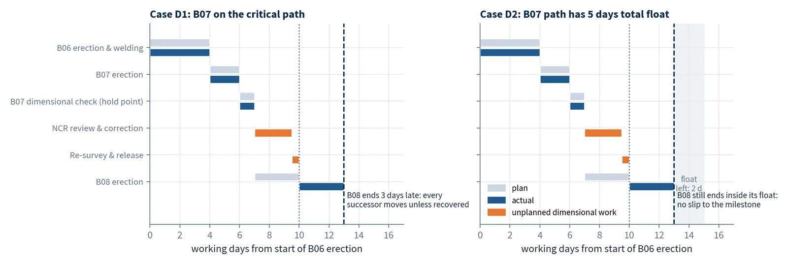
- Case D1, critical path: B08 erection finishes three days late, and under the stated assumptions every successor moves by the same amount.
- Case D2, five days of total float: B08 still finishes within its float and the milestone holds. The float on the path falls from five days to two, leaving less margin for other delays.
From a project management perspective, dimensional deviations should be recorded and assessed not only as quality issues but also as potential schedule and cost risks. Recording the float consumed alongside the non-conformity makes that risk visible. For more on float and erection sequencing, see hull block construction sequencing and critical path management and the critical path method lesson.
Integrating Keel Surveys into Shipyard Project Management
Linking survey activities to the construction schedule
Keel sighting and deflection surveys should be included in the construction schedule at appropriate milestones, with time allowed for:
- survey preparation and access arrangements;
- execution of the measurements;
- evaluation of the results;
- engineering review where necessary;
- corrective action, if required;
- follow-up inspection and release.
For major block erection activities, dimensional inspection and acceptance may be necessary before the next operation can proceed. Including these activities in the schedule improves the visibility of inspection requirements and reduces the risk of unplanned delays. Where the measurement procedure specifies a particular time of day, that also becomes a resource and access question for planning. See also building the hull block construction schedule.
Inspection and test plans
Survey activities can be incorporated into the project's Inspection and Test Plan (ITP). The ITP should identify the relevant inspection stage, responsible parties, acceptance criteria, required records and any classification surveyor involvement.
IACS UR Z23 defines the survey methods in which the class surveyor is directly involved: patrol (checking on an independent and unscheduled basis that processes continue to conform), review (examining documents) and witness (attendance at scheduled inspections in accordance with the agreed ITP). Depending on the project, inspection points in the ITP may also be designated as review, witness or hold points. Where the approved inspection plan makes an inspection a hold point, the next construction activity should not start until formal release. For more on how class surveys fit into a build, see quality assurance and classification society surveys.
Survey records and traceability
A complete survey record should include sufficient information to reproduce and evaluate the measurement:
| Field | Example entry (hypothetical) |
|---|---|
| Vessel and construction stage | Hull NB-xxx, after upper deck erection butts, blocks B01 to B10 |
| Date, start and end time | 2026-mm-dd, hh:mm to hh:mm |
| Surveyor and team | name, role |
| Instrument, serial no., calibration and field check | total station, s/n, calibration certificate no., date of last field check |
| Datum and survey point references | construction datum; P0 to P10 at listed frames |
| Measured coordinates or heights | table of raw readings |
| Reference line and relative deflection | method used (e.g. line through P0 and P10) and resulting values |
| Support condition | keel block plan revision, blocks removed or added since last survey |
| Loading condition | major items installed or removed since last survey, temporary loads |
| Environment | weather, relevant structural temperatures |
| Acceptance criterion and source | e.g. project dimensional control procedure, clause reference |
| Deviations and evaluation | comparison with previous survey, internal trigger exceeded yes/no |
| Actions and follow-up | non-conformity reference, re-survey reference |
To keep these records and the relative deflection calculation in one place, you can download the Keel Deflection Survey Record & Profile Workbook (free, xlsx). It converts raw heights to deflection relative to a reference line, compares successive surveys, runs local checks between two points and plots the profile. It comes with the hypothetical Scenario A data as a worked example, and its trigger and acceptance criterion fields are left blank for your project to fill in.
Results should be presented in a format that allows comparison between successive surveys. A longitudinal profile chart such as Figure 5 can show the measured geometry and its change over time, provided it clearly distinguishes measured values from the design reference and from any acceptance limits.
Responsibilities and communication
Effective dimensional control requires cooperation between several departments.
| Team | Contribution |
|---|---|
| Survey team | establishes the reference, performs measurements, prepares the survey report |
| Production | provides the construction sequence, welding progress, temporary supports and loading condition |
| Welding engineering | evaluates welding-related distortion, recommends procedures and sequence adjustments |
| Quality control | verifies compliance with inspection requirements, manages non-conformities |
| Project planning | incorporates inspections and possible corrective work in the schedule, monitors float consumed |
| Project management | coordinates decisions where deviations may affect cost, schedule, technical compliance or delivery |
Clear communication is particularly important when a survey identifies a deviation that could affect upcoming construction activities.
Practical Example: Monitoring Deflection During Block Erection
The hypothetical hull of Scenario A is under construction in a dry dock. After block setup, the survey team records the heights of P0 to P10 (Survey 1). After the erection of the major blocks, Survey 2 shows 18 mm of relative sag at midship. The raw readings suggested 25 mm, but 7 mm of that was settlement and tilt. The result is below the project's hypothetical 25 mm investigation trigger and is recorded.
After the upper deck erection butts have been welded, Survey 3 shows 33 mm of relative sag at midship, 15 mm more than Survey 2. The trigger is exceeded, and the review follows the control loop. At this point the cause is unknown. Deck welding is one possible contributing factor, but it is only one candidate, and it is not examined until the other explanations have been checked.
- Verify the measurement. The team re-observes the end points P0 and P10 and a selection of intermediate points from a second instrument set-up, confirms the instrument's field check and the target positions, and estimates the uncertainty of the survey for the actual distances and conditions. It also confirms that the end points themselves have not moved locally, since an end-point error would be distributed along the whole profile.
- Compare the thermal conditions. The recorded structural temperatures and times of Surveys 2 and 3 are compared. If they differ materially, part of the change may be thermal, and a repeat survey under conditions matching Survey 2 is taken before any further conclusion.
- Check support conditions. The keel block plan and the block records are checked for removed, adjusted or settled blocks since Survey 2. In this example, the raw readings at P0 and P10 are unchanged from Survey 2, which is consistent with no further settlement or tilt, but the block records are still checked, including blocks near midship.
- Check loading. Items installed or removed, temporary loads and equipment placed on the hull since Survey 2 are listed with their approximate positions and weights.
- Review the construction activity. Only after steps 1 to 4 does the team consider welding. The welding engineer reviews which seams were welded between the two surveys, in what sequence, and whether the shrinkage recorded for similar joints is of an order that could contribute to the observed change. Scenario C shows that deck-bottom differential shrinkage is geometrically capable of producing changes of this order, but that does not establish it as the cause.
- Agree actions. The team agrees proportionate actions based on what the checks found. These may include continued monitoring with an additional survey after the next welding stage, a review of the planned sequence for the remaining seams by the welding engineer, confirmation that no supports will be altered before the next survey, and a check of the result against the acceptance criterion agreed with class. No structural correction is proposed unless the applicable criterion is exceeded or the engineering review requires it.
- Verify. The next survey is compared with Survey 3 under documented conditions. If the profile has stabilised, the result is recorded and the survey programme continues. If the change continues, the diagnosis is reopened.
This example illustrates how survey information can support construction decisions. It does not imply that a particular cause, welding sequence or corrective action applies to every vessel.
Best Practices for Effective Keel Deflection Control
- Establish a consistent reference system. Use clearly identified survey points and a documented datum throughout the relevant construction stages.
- Define the reference line. State how relative deflection is calculated (for example, against a line through defined end points), keep the end points on stable structure, and use the same method for every survey.
- Separate settlement and tilt from bending. Report deflection relative to the reference line before interpreting the results.
- Record the actual construction conditions. Measurements should be accompanied by information about loading, supports, time of day and relevant temperatures.
- Take comparable surveys under comparable conditions. Define the timing and thermal conditions in the measurement procedure.
- Use appropriate measurement equipment. Select the instrument and procedure according to the required accuracy, and estimate uncertainty for the actual set-up.
- Plan surveys around construction milestones. Focus on stages where structural loading, welding or assembly may significantly affect hull geometry.
- Evaluate trends rather than isolated readings. Repeated measurements help distinguish meaningful changes from measurement variation and temporary deformation.
- Verify before attributing. Check measurement, temperature, supports and loading before attributing a change to welding or any other activity.
- Coordinate dimensional control with welding engineering. Survey results should be considered when reviewing welding sequences and possible distortion mechanisms.
- Avoid universal assumptions about corrective welding. Corrective measures must be based on engineering evaluation and the approved construction procedures.
- Apply project-specific acceptance criteria. Identify the criterion and its source for each check; do not assume that a single numerical tolerance applies to every hull structure or construction stage.
- Maintain traceable records. Keep measurement results, evaluations, corrective actions and follow-up surveys available for review.
- Integrate quality control with project planning. Ensure that inspection, engineering review, possible rework and float consumed are visible in the construction schedule.
Conclusion
Keel sighting and keel deflection surveys are important elements of dimensional control during ship construction. They provide information about the longitudinal geometry of the hull and help identify changes associated with structural loading, support conditions, welding shrinkage, temperature and construction activities.
Their value extends beyond the survey itself. When measurement results are consistently recorded and communicated, they can support decisions about block erection, welding sequences, machinery installation and corrective actions.
Reliable dimensional control requires more than accurate instruments. It depends on a consistent reference system, measurements taken under comparable and documented conditions, a clearly defined reference line, an understanding of structural and thermal behaviour, and the careful interpretation of trends. The worked scenarios illustrate that settlement, tilt and temperature can each produce changes in readings that are comparable in size to the effects a survey is intended to detect, which is why measurements must be verified before causes are assigned.
Welding sequence planning can help reduce distortion, but it must be developed for the actual joints and structure, and it cannot be relied on to reverse deflection that has already occurred. Dimensional acceptance must be based on the requirements agreed for the project, with Rec. 47 or the accepted fabrication standard as the reference and the classification society deciding where the standard gives no limit.
For shipyards, integrating dimensional surveys with production planning, welding engineering and quality control provides a systematic way to manage construction risks, reduce avoidable rework and maintain control of the vessel's geometry throughout the building process.
References and Further Reading
- IACS Recommendation No. 47, Shipbuilding and Repair Quality Standard, Rev. 10 Corr. 1 (October 2025), Part A: section 1 (Scope), Table 6.5 (line heating), Table 6.6 (block assembly), Table 6.7 note (main engine bed), Tables 6.8 and 6.9 (shape). iacs.org.uk; clean text PDF
- IACS Unified Requirement Z23, Hull Survey for New Construction, Rev. 7 Corr. 2 (May 2023): section 2.3 (patrol, review, witness), section 7.4 (quality standards), Table 1 item 3 (steelwork process). iacs.org.uk
- ABS, Guidance Notes on Propulsion Shafting Alignment (April 2006, updated February 2014), Sections 1 and 3: disturbances to alignment, sighting through, dry dock and afloat alignment. eagle.org
- TWI, Distortion: Types and Causes. twi-global.com
- TWI, Distortion Control: Prevention by Fabrication Techniques. twi-global.com
- TWI, Distortion: Prevention by Design. twi-global.com
- TWI, Distortion: Prevention by Pre-setting, Pre-bending or Use of Restraint. twi-global.com
- TWI, Distortion: Corrective Techniques. twi-global.com
- EN 1993-1-1, Eurocode 3: Design of steel structures, Part 1-1, clause 3.2.6 (coefficient of linear thermal expansion).
- ISO 17123-3 (theodolites) and ISO 17123-5 (total stations), Field procedures for testing geodetic and surveying instruments. iso.org
About the numbers in this article
All four scenarios use a hypothetical 150 m hull. The survey values, temperature differences, shrinkage values, investigation trigger and schedule durations are constructed or assumed to show the arithmetic. They are not measured data, not predictions for a real vessel and not recommended values. Criteria quoted from IACS Rec. 47 and UR Z23, and procedures from ABS and TWI, are cited to the sources above. Numerical tolerances, survey intervals and corrective procedures for a real vessel come from its approved drawings, project specification, classification requirements and the yard's documented procedures.