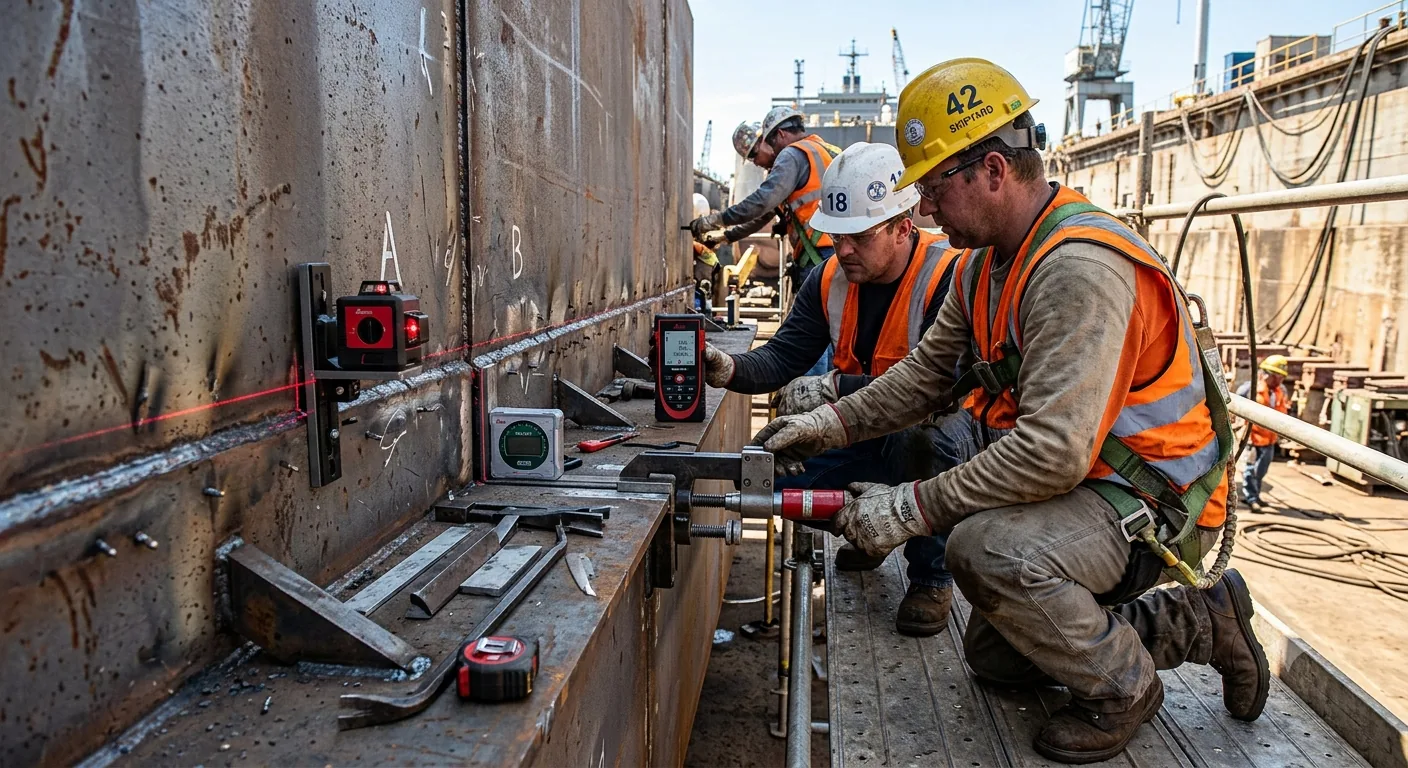
The Hull Block Construction Method (HBCM) has become the dominant paradigm in modern shipbuilding worldwide. By dividing the hull into manageable three-dimensional blocks that are fabricated in parallel, extensively pre-outfitted, and then erected in a carefully optimized sequence, shipyards achieve dramatic reductions in dock time, improvements in quality, and significant cost savings. This lesson gives shipyard professionals an in-depth understanding of block construction principles, detailed erection sequencing methodologies, optimization techniques, quality control requirements, and the integration of modern digital tools including 4D scheduling and ERP systems.
The document covers the full lifecycle from initial block division strategy through fabrication, pre-outfitting, transportation, erection, alignment, welding, and final quality assurance. Special attention is given to the critical topic of erection sequencing optimization, which directly determines project makespan and resource utilization. Practical examples are drawn from typical Offshore Patrol Vessel (OPV) and similar medium-sized newbuild projects commonly executed in Turkish and international shipyards.
Key recommendations include maximizing pre-outfitting levels to Level 3 where feasible, developing robust Work Breakdown Structures aligned with production constraints, using simulation-based sequencing optimization, and integrating 3D models with scheduling tools for real-time progress visualization. The guide also addresses common challenges such as distortion control, interface management, crane and space conflicts, and provides mitigation strategies based on industry best practices.
1. Introduction and Historical Evolution of Block Construction
Shipbuilding has undergone a profound transformation over the past six decades. In the mid-20th century, most vessels were still constructed using traditional methods where individual steel plates and sections were erected directly onto the ways or in dry dock, one after another. This sequential approach resulted in long construction cycles, heavy dependence on weather conditions, limited opportunities for pre-outfitting, and significant quality variability. The introduction of the Hull Block Construction Method (HBCM) revolutionized the industry by enabling parallel production streams and modular assembly.
The origins of modern block construction can be traced to Japanese shipyards in the 1960s and 1970s, where pioneering yards such as Mitsubishi, Ishikawajima-Harima, and Nippon Kokan began experimenting with larger prefabricated units to reduce dock occupancy time. The method gained widespread adoption in Korean shipyards during the 1980s and 1990s as Hyundai, Samsung, and Daewoo scaled up production of very large crude carriers (VLCCs) and container ships. European yards followed, adapting the approach for complex vessels including cruise ships, ferries, and naval vessels. Today, HBCM is the global standard for virtually all commercial and naval newbuild programs exceeding approximately 50 meters in length.
The fundamental principle is simple yet powerful: divide the ship into logical three-dimensional blocks that can be built independently in workshops or on panel lines, complete as much outfitting as possible at the block stage, and then assemble these blocks in the building dock or on the slipway in an optimized sequence. This approach shifts the majority of work from the constrained dock environment to more efficient workshop conditions, improves worker safety and productivity, and allows multiple blocks to progress simultaneously.
In the Turkish shipbuilding context, particularly in the Yalova and Tuzla regions, the adoption of advanced block construction practices has accelerated in recent years. Yards building offshore patrol boats, coast guard vessels, ferries, and special-purpose ships are increasingly implementing structured WBS-based planning, higher pre-outfitting targets, and digital scheduling tools. The methodology described in this guide is directly applicable to these projects and can be integrated with local ERP systems tailored to the specific needs of tersane operations.
2. Fundamentals of the Hull Block Construction Method (HBCM)
The Hull Block Construction Method organizes ship production into a hierarchical structure of assemblies. At the lowest level are individual parts (plates, profiles, brackets). These are combined into panels and sub-assemblies on dedicated panel lines or in assembly bays. Panels and sub-assemblies are then joined to form complete three-dimensional blocks. Blocks may be further combined on the ground into grand blocks or mega blocks before final erection. The completed blocks are transported to the erection site (dry dock or slipway), positioned with high precision, aligned, and permanently joined through welding.
The primary advantage of HBCM lies in the ability to perform work in parallel. While one block is being fabricated in the workshop, another is undergoing outfitting, a third is being painted, and a fourth is already erected in the dock. This parallelism dramatically compresses the overall project schedule compared to traditional sequential construction. Additionally, working in controlled workshop environments improves weld quality, reduces rework, and enhances safety by minimizing work at height and in exposed conditions.
A secondary but equally important benefit is the opportunity for extensive pre-outfitting. In traditional construction, most piping, cabling, HVAC, and machinery installation occurs after the hull is closed up, in cramped and difficult conditions. In block construction, these systems can be installed while the block is still open and accessible, often before the block even leaves the workshop. Leading shipyards target pre-outfitting levels of 70-85% for machinery spaces and 50-70% for other areas, resulting in significantly shorter dock periods and higher overall productivity.
3. Block Hierarchy, Definition, and Division Strategies
Block Hierarchy Levels
A well-defined hierarchy is essential for effective planning and control. The typical structure used in modern shipyards is as follows:
- Part / Component: Individual steel plates, rolled sections, brackets, and fittings after cutting and edge preparation.
- Panel / Sub-assembly: Flat or curved stiffened panels produced on panel lines, including attached brackets and minor foundations.
- Block: A three-dimensional structural unit typically weighing 50–400 tons, formed by joining multiple panels and sub-assemblies. Examples include bow blocks, stern blocks, engine room blocks, and side shell blocks.
- Grand Block / Mega Block: Two or more blocks joined on the ground or in a pre-erection area to form a larger unit (often 400–1,200+ tons). This reduces the number of critical lifts in the dock.
- Module / Super Block: A highly outfitted grand block or complete functional unit (e.g., fully outfitted engine room module) ready for integration.
Criteria for Block Division
Determining the optimal block breakdown is one of the most important planning decisions in a newbuild project. The division must balance multiple, often conflicting, objectives. Key criteria include:
- Structural Integrity and Welding Efficiency: Blocks should be designed so that critical structural members are contained within a single block where possible, minimizing high-stress butt joints across block boundaries.
- Crane Capacity and Lifting Geometry: Maximum block weight and dimensions are constrained by the heaviest lift capacity of dock cranes or gantry cranes, including dynamic factors and outreach.
- Transportation Limits: Internal roads, gate widths, SPMT configurations, and turning radii limit the maximum size that can be moved from the workshop to the dock.
- Pre-outfitting Targets: Blocks intended for high levels of outfitting (especially machinery and technical spaces) should be sized to allow good access for fitters and welders.
- Erection Sequence Logic: The division must support a logical erection sequence that respects structural stability, alignment requirements, and critical path activities.
- Production Area Capacity: Available panel line throughput, assembly bay space, and workforce distribution influence how work is packaged into blocks.
- Interface Management: Block boundaries should be located where alignment is easier to control and where welding can be performed efficiently from both sides if possible.
Example Block Division for a 90m Offshore Patrol Vessel
For a typical 90-meter Offshore Patrol Vessel (OPV) with a displacement of approximately 2,000–2,500 tons, a practical block breakdown might consist of 55–75 blocks, grouped into 12–18 grand blocks. The bow section (approximately 15–18 m) may be divided into 4–6 blocks including the bulbous bow, sonar dome, and forecastle. The engine room area (often the most complex) may be split into 6–8 blocks to facilitate high pre-outfitting. The stern section including the flight deck and steering gear may comprise 5–7 blocks. Side shell blocks are typically symmetric port and starboard to simplify production. This division allows parallel fabrication while respecting crane capacities of 300–600 tons commonly available in mid-sized Turkish yards.
4. Detailed Block Fabrication Process
Block fabrication encompasses all activities from raw material receipt through to a completed, painted, and inspected three-dimensional unit ready for transportation. The process is typically executed in a combination of automated panel lines, semi-automated assembly bays, and manual fitting/welding stations.
Material Preparation and Cutting
Steel plates (commonly Grade A, AH36, DH36, EH36 or higher for naval vessels) arrive with mill certificates. Plates are first inspected for surface defects and laminations. CNC nesting software optimizes plate utilization to minimize scrap. Cutting is performed using high-definition plasma, fiber laser, or waterjet systems. Edge preparation (beveling for welding) is often integrated into the cutting process using 5-axis or 6-axis robotic heads. Dimensional tolerance after cutting is typically held to ±1.0 mm for critical edges.
Panel and Sub-Assembly Fabrication
Stiffened panels are the building blocks of blocks. On modern panel lines, plates are positioned, stiffeners (longitudinals and transverses) are fitted automatically or semi-automatically, and fillet welds are completed by welding gantries or robots. Typical panel sizes range from 3 m × 12 m up to 4 m × 16 m depending on the yard’s equipment. Curved panels for bow and stern areas require specialized forming and assembly jigs. Sub-assemblies such as web frames, brackets, and minor foundations are fabricated in parallel and then integrated into the main panels.
Figure 3: Profile storage, cutting, and loading systems integrated with panel assembly lines. Efficient material handling is critical to maintaining high panel line utilization.
Block Assembly, Welding, and Fairing
Block assembly takes place in dedicated bays equipped with heavy lifting capacity (50–200 tons), strongbacks, and alignment tools. Panels are erected vertically or horizontally depending on the block orientation and then joined with butt and fillet welds. Internal structure (decks, bulkheads, girders, foundations) is fitted and welded. Throughout assembly, fairness is continuously monitored using laser trackers or total stations. Distortion is controlled through balanced welding sequences, back-step techniques, and temporary restraints. Upon completion of structural welding, non-destructive testing (NDT) is performed according to the class society requirements and the yard’s quality plan.
Surface Preparation and Coating
After structural completion and NDT clearance, blocks undergo surface preparation (blasting to Sa 2.5 or better) and application of the coating system. Most yards apply a shop primer immediately after cutting for corrosion protection during fabrication, followed by the full system (epoxy, polyurethane, or specialized anti-fouling for underwater areas) at the block stage. Proper coating at the block stage significantly reduces the amount of touch-up and repair work required after erection.
5. Pre-Outfitting Philosophy and Implementation Levels
Pre-outfitting is the single most powerful lever for reducing dock time and improving overall project economics. The guiding principle is simple: perform as much work as possible while the block is still open, accessible, and in a comfortable workshop environment, rather than after it has been erected and the spaces are confined.
Pre-Outfitting Levels
Industry practice commonly defines four progressive levels of pre-outfitting:
- Level 1: Structural Only: Block contains only steel structure, foundations, and major penetrations. Minimal systems work.
- Level 2: Basic Systems: Addition of major pipe runs, cable trays, HVAC ducting, and primary foundations. Typical for hull and deck blocks.
- Level 3: Advanced Systems: Complete piping systems with valves and fittings, electrical distribution, lighting, insulation, and equipment installation. Standard target for engine room and technical blocks.
- Level 4: Commissioning Ready: Systems are pressure tested, functionally tested, and ready for integration testing after erection. Achieved in the most advanced yards for selected modules.
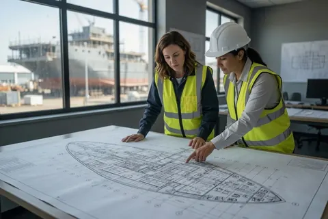
For an OPV project, realistic targets might be Level 3 for the engine room and auxiliary machinery blocks, Level 2.5 for accommodation and operational spaces, and Level 2 for hull and deck blocks. Achieving these targets requires early coordination between engineering, planning, and production teams to ensure that design information (piping isometrics, cable schedules, equipment layouts) is released in time to support block-level work.
6. Block Transportation, Handling, and Pre-Erection Area Management
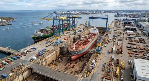
Once a block is completed, painted, and inspected, it must be moved from the fabrication area to a pre-erection staging area or directly to the dock. Safe and efficient handling of large, heavy, and often irregularly shaped blocks is a specialized discipline. Most yards use self-propelled modular transporters (SPMTs), heavy-lift trailers, or rail-mounted systems. Lifting is performed with gantry cranes, floating cranes, or the main dock cranes.
The pre-erection area serves as a buffer and sequencing zone. Blocks are positioned in the order they will be erected, allowing final checks, minor repairs, and attachment of lifting lugs or strongbacks. Space management in this area is critical; poor layout leads to double-handling and delays. Some yards use 4D simulation to plan the exact positioning and movement of blocks through the pre-erection zone to avoid congestion.
7. Erection Sequencing: Principles, Dependencies, and Optimization
Erection sequencing is the heart of the production schedule. The sequence in which blocks are lifted into the dock and joined determines the critical path, resource loading, and overall project duration. A well-optimized sequence minimizes makespan while respecting all technical and logistical constraints.
Fundamental Sequencing Rules
- Bottom-Up Principle: Blocks are erected from the keel upwards. Double-bottom and lower side shell blocks precede upper side shell and deck blocks.
- Centerline First: Centerline or near-centerline blocks are usually erected before port and starboard side blocks to provide a stable reference for alignment.
- Bow and Stern Priority: These complex blocks often lie on or near the critical path and should be erected early enough to allow follow-on work (rudder, propeller, sonar) to proceed without delay.
- Engine Room Early Integration: Because of the high density of systems and heavy equipment, the engine room block(s) should be erected sufficiently early to allow machinery installation and alignment before surrounding structure closes in.
- Stability During Erection: The partial hull must remain stable and able to resist wind, wave (if applicable), and construction loads at every stage.
Optimization Techniques
Modern planning departments use a combination of experience-based rules and quantitative optimization methods. Simple projects may be sequenced manually using precedence diagrams and critical path method (CPM) scheduling. More complex projects benefit from mathematical modeling. Common approaches include:
- Mixed-Integer Linear Programming (MILP): Models the sequence as a set of binary variables representing the order of erection activities, subject to constraints on crane availability, space, lifting times, joining times, and precedence relationships. The objective is typically to minimize total makespan.
- Discrete Event Simulation: Simulates the entire erection process including stochastic elements (weather delays, equipment breakdowns, rework). Useful for testing robustness of a proposed sequence.
- Genetic Algorithms and Metaheuristics: Effective for large combinatorial problems where exact MILP solvers become computationally expensive.
Regardless of the method chosen, the model must incorporate realistic durations for lifting, positioning, alignment, fit-up, root welding, and subsequent passes. It must also respect the physical constraints of the specific dock and crane configuration.
Integration with Overall Project Schedule
The block erection schedule is the master schedule from which all other production schedules are derived. Block fabrication, outfitting, and coating schedules are backward-planned from the erection dates. Procurement of long-lead items (main engines, gearboxes, generators, sonar domes) must also be aligned with the erection sequence. Any delay in block readiness directly impacts the erection schedule and, ultimately, the delivery date. Therefore, the erection sequence must be realistic, with appropriate buffers at key milestones, and it must be updated regularly based on actual progress.
8. Alignment, Welding, NDT, and Quality Assurance during Erection
Erection is not merely a matter of lifting blocks into place; it is a precision operation requiring tight control of alignment, fit-up, and welding to achieve the required structural fairness and integrity.
Alignment Control
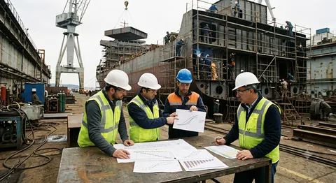
Modern yards use laser trackers, total stations, and photogrammetry systems to establish a 3D coordinate network for the entire dock. Each block is surveyed in its landed position and adjusted using hydraulic jacks, temporary supports, or strongbacks until it meets the required alignment tolerances. Typical tolerances for butt joints are 1–2 mm misalignment and 3–5 mm gap. Fairness of the hull form is usually controlled to within 5–10 mm over 1 meter, depending on class society requirements and vessel type. Continuous monitoring during welding is essential because heat input can cause movement.
Welding During Erection
Welding sequences for block joints must be carefully planned to minimize distortion and residual stress. Common practices include balanced welding from both sides where accessible, back-step or skip welding to distribute heat, and the use of temporary strongbacks or clamps to restrain movement. Welding procedure specifications (WPS) and welder qualification records (WPQR) must be current and appropriate for the joint type, position, and material grade. Root passes are typically inspected before proceeding with fill and cap passes.
Non-Destructive Testing and Survey
All critical erection joints are subjected to NDT according to the approved inspection and test plan (ITP). Ultrasonic testing (UT) is the most common method for butt joints in plate thicknesses above 10–12 mm. Magnetic particle testing (MT) or penetrant testing (PT) is used for fillet welds and surface-breaking defects. Radiographic testing (RT) may be required for certain high-stress or inaccessible joints. Class surveyors witness or review a defined percentage of NDT results. Any defects are repaired and re-tested before proceeding.
9. Production Planning Tools, 4D Scheduling, Digital Twins, and ERP Integration
Effective block construction and erection sequencing cannot be managed with spreadsheets alone. Modern shipyards employ integrated digital platforms that connect 3D product models, scheduling, resource management, and progress tracking.
3D Model and 4D Scheduling
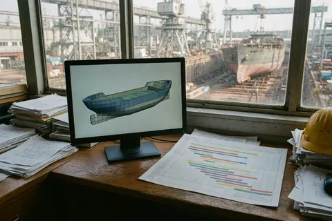
A detailed 3D model of the entire vessel, broken down into blocks, is the foundation. Each block is linked to schedule activities in a 4D scheduling environment (e.g., Synchro, Navisworks, or similar). The planner can visualize the erection sequence over time, identify spatial conflicts, and communicate the plan clearly to all stakeholders. 4D models are also powerful tools for reviewing the impact of proposed changes or delays.
ERP and Production Management Systems
Enterprise Resource Planning systems tailored for shipbuilding integrate material management, work order generation, progress recording, and cost control. When the block erection schedule is the master schedule, the ERP can automatically generate fabrication and outfitting work orders with realistic start and finish dates based on the erection sequence. Real-time progress feedback from the shop floor allows planners to identify deviations early and take corrective action.
Digital Twin and Real-Time Visualization
Leading yards are moving toward digital twin implementations where the as-built status of each block is continuously updated from sensors, laser scans, and manual progress entries. The digital twin provides a single source of truth for all stakeholders and supports advanced analytics such as predictive delay identification and resource optimization.
10. Common Challenges, Risks, and Mitigation Strategies
Even with excellent planning, block construction projects encounter challenges. The most frequent issues and proven mitigation approaches are summarized below.
- Optimistic Duration Estimates: Mitigation: Use historical productivity data adjusted for learning curves and complexity factors. Include contingency at the activity level and management reserve at the project level.
- Block Interface Misalignment: Mitigation: Perform 3D clash detection during detailed design. Conduct mock-up trials for critical interfaces. Allow time in the erection schedule for fit-up adjustments.
- Crane and Space Conflicts: Mitigation: Develop a detailed daily lifting plan. Use simulation to validate the sequence. Maintain a well-organized pre-erection area with clear access routes.
- Welding Distortion: Mitigation: Apply balanced and controlled welding sequences. Use temporary strongbacks and restraints. Monitor alignment continuously during welding.
- Late Design Changes: Mitigation: Freeze block boundaries and major system layouts early. Implement a strict change control process with impact assessment on the erection schedule.
- Material and Equipment Delays: Mitigation: Maintain a critical items list with long lead times. Build buffers into the schedule for high-risk items. Develop alternative sourcing strategies.
11. Case Studies and Industry Best Practices
Leading international shipyards consistently demonstrate that disciplined application of the principles described in this guide yields measurable results. Korean and Chinese yards building large container ships and LNG carriers routinely achieve dock periods of 4–6 months for vessels exceeding 300 meters through extensive use of mega blocks (some over 1,000 tons) and very high pre-outfitting levels. European yards constructing complex cruise ships and ferries emphasize detailed 4D planning and digital twin technology to manage thousands of blocks and modules with extreme precision.
In the Turkish context, yards that have invested in structured WBS development, higher pre-outfitting targets, and integrated planning tools report dock time reductions of 20–35% compared with traditional methods on similar vessel types. The key success factors observed across these yards include strong collaboration between planning, engineering, and production departments; realistic scheduling based on measured productivity; and continuous updating of the erection sequence based on actual progress.
12. Future Trends: Automation, Sustainability, and AI in Block Construction
The evolution of block construction continues. Robotic welding gantries and automated panel lines are already common; the next wave includes greater use of collaborative robots for fitting and welding in confined spaces, automated guided vehicles for block transportation, and AI-assisted planning systems that can rapidly generate and evaluate thousands of possible erection sequences. Sustainability considerations are driving interest in reduced material handling (lower energy and emissions), optimized nesting to minimize scrap, and the use of lower-carbon steel grades. Digital twins and IoT sensors will provide ever-richer data for real-time decision making and predictive maintenance of production assets.
13. Conclusion and Recommendations
Block construction and erection sequencing represent the core competitive capability of any modern shipyard. When executed with discipline and supported by appropriate digital tools, the methodology delivers shorter delivery times, lower costs, higher quality, and improved safety. The recommendations emerging from this guide are clear: invest in robust Work Breakdown Structures aligned with production realities; set ambitious but achievable pre-outfitting targets; develop and continuously optimize the erection sequence using quantitative methods; integrate 3D models with scheduling and ERP systems; and maintain rigorous alignment and quality control during erection. Shipyards that master these practices will be well positioned to win and execute complex newbuild projects successfully in an increasingly competitive global market.
References and Further Reading
- Tokola, H.A. et al., Block Erection in the Event of Delays in Shipbuilding (Journal of Ship Production and Design, 2016)
- Roh, M.I. et al., Generation of production material information for a building block (International Journal of Production Research, 2007)
- Various authors, Hull Block Construction Method literature and shipyard case studies (ResearchGate, Springer, industry publications)
- Class Society Rules: ABS, DNV, Bureau Veritas, Hull Construction and Welding Requirements
- Project2Me.com technical articles on hull block construction scheduling (2026)
See also: Shipbuilding Project Lifecycle: An Overview, and Pre-Outfitting Strategy: Maximizing Block-Stage Work.