
Ship newbuilding remains one of the most complex project environments in heavy industry. A single vessel can involve tens of thousands of components, hundreds of concurrent work packages, multiple engineering disciplines (welding, piping, electrical, painting) working in confined spaces, long-lead equipment with delivery windows measured in months, and extremely limited physical resources such as drydocks, gantry cranes, and skilled labor.
Unlike most construction or manufacturing projects, the product itself moves through successive physical locations, from steel cutting and panel lines, through block assembly halls, to the slipway or drydock for erection, and finally to the outfitting quay. Throughout this journey, the production schedule must continuously adapt to design changes, material delays, supply chain disruptions, and strict classification society requirements.
At the center of successful delivery sits the production schedule, and at the core of that schedule is the sequence of hull block construction and erection. Getting the block sequence wrong creates cascading delays that no amount of overtime or additional manpower can easily recover. Conversely, getting the critical path wrong means the project team spends months chasing the wrong activities while the true drivers of the delivery date remain hidden.
This article provides a comprehensive, practical treatment of hull block construction sequencing and critical path management from an operational perspective. It is written for project planners, production managers, planning engineers, and yard superintendents who need to move beyond generic project-management theory and apply these methods in a real shipyard environment.
The Product-Oriented Work Breakdown Structure (PWBS) as the Foundation
Any credible production schedule begins with a product-oriented work breakdown structure. In shipbuilding, this is commonly called the PWBS (Product Work Breakdown Structure) or, depending on the yard's tradition and the classification society's preference, the SWBS (Ship Work Breakdown Structure). Modern shipyards often integrate these two into a matrix structure.
A well-constructed PWBS does three essential things:
- It decomposes the vessel into manageable, measurable units of work that can be planned, estimated, scheduled, and controlled.
- It creates a common language across design, procurement, production, and quality departments.
- It provides the structural backbone for the network logic that will later determine the critical path.
Deep Dive into Hierarchical Levels
A typical PWBS for a commercial or naval newbuild follows this hierarchy:
- Level 0: The Complete Ship (The project itself)
- Level 1: Major Product Groups (Hull Structure, Main Machinery, Electrical, Outfitting, Paint & Preservation)
- Level 2: Zones or Functional Systems (Forward Hull, Cargo Hold Zone, Engine Room, Superstructure, etc.)
- Level 3: Blocks or Major Assemblies (Block A12, Block B07, Engine Room Module ER-01)
- Level 4: Sub-assemblies, Panels, and Advanced Outfitting Modules
- Level 5: Individual Work Packages or Operations (Profile cutting, panel welding, pipe installation within a block, cable tray pulling, etc.)
For scheduling and management purposes, the most critical levels are usually Level 3 (blocks) and Level 4 (major sub-assemblies). The network activities in the master schedule are fed from these levels.
Block Definition Principles and Design Constraints
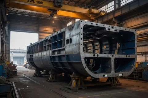
Blocks are not merely geometric pieces; they are production units optimized according to the shipyard's capacity. They must be defined according to the following practical rules:
- Crane Capacity and Lifting Weight: A block that exceeds the capacity (and safe working limits under wind load) of the available gantry or floating crane is useless. The weight of lifting slings (rigging) and transport equipment must also be factored in.
- Transportation and Handling Constraints: The block must be transportable from the assembly hall to the erection site (slipway or drydock) without requiring temporary stiffening that itself becomes a major work package.
- Advanced Outfitting Density: Highly outfitted blocks, especially machinery and accommodation spaces, should be completed as much as possible before erection (e.g., while the block is upside down or still in the hall). This meaningfully reduces the harder, slower working conditions of finishing the same installation on board after erection.
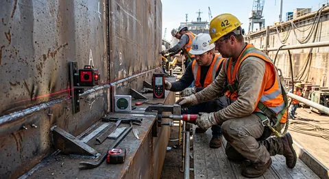
- Dimensional Accuracy and Alignment: Blocks that form critical alignment planes (keel, sheer strake, main engine foundations) require tighter tolerances. Lazer measurement (dimensional control) steps must be included in the planning.
- Trade Access and Safety: Once erected, some blocks become difficult or unsafe for certain trades to access. For example, scaffolding removal and final touch-up painting must be completed before large tanks are closed off.
- Tugboat / small naval vessel: roughly 30-80 tons per block, typically built in traditional indoor halls with mobile cranes.
- Mid-size chemical tanker / OPV: roughly 100-250 tons per block, standard gantry cranes and panel lines.
- Large container ship / cruise ship: 400-1000+ tons per block, mega-block construction with Goliath gantry cranes.
These figures vary meaningfully by yard and vessel design, they're a rough sense of scale rather than a fixed standard.
Extended Example PWBS: 90-Meter Offshore Patrol Vessel (OPV)
Consider a 90-meter OPV with a steel weight of approximately 1,800 tons. A detailed Level 3 block list would include:
- Aft Zone: A01 (Aft keel block including propeller shaft bosses), A02 (Aft bottom block), A03-A04 (Port/Starboard aft side blocks).
- Machinery Zone: M01 (Main engine seating and double bottom), M02 (Auxiliary machinery and generator room), M03 (Engine room upper platforms).
- Midship Zone: B01-B08 (Mission bay, fuel tanks, stabilizer recesses).
- Forward Zone: C01 (Stem block and sonar dome housing), C02-C06 (Bow thruster room and chain locker).
- Superstructure: S01 (Accommodation lower deck), S02 (Bridge), S03 (Aluminum mast and radar foundation).
Logical Sequencing Rules for Block Erection
Once blocks are defined, the planner must establish the logical relationships (network logic) that govern the order of erection. This sequence is the heartbeat of the project.
Fundamental Precedence Types
The relationships commonly used in shipbuilding networks include:
- Finish-to-Start (FS): The most common. Block B cannot be placed on the slipway until Block A is completely erected and aligned.
- Start-to-Start (SS) with Lag: Two adjacent blocks can begin concurrent outfitting work once a certain distance (e.g., a minimum of 30% of the welding operations) is completed. This is a critical relationship for managing welding shrinkage.
- Finish-to-Finish (FF): Used for tests that must be completed simultaneously or painting work required prior to drydock flooding or launching.
- Start-to-Finish (SF): Rare in shipbuilding and generally avoided to prevent confusion.
Advanced Sequencing Principles
- Keel and Centerline First: The keel blocks establish the reference plane for the entire ship. Laser stations are set up based on this reference; everything else is measured from this line.
- Bottom-Up and Center-Out: After the centerline is established, side blocks and upper blocks are erected in a controlled sequence to maintain dimensional accuracy and minimize welding distortion.
- Structural Continuity Before Heavy Outfitting: Primary structural joints must be completed and approved by the class society before heavy outfitting items (main engines, shaft, large pumps) are placed. Otherwise, hull flexing will ruin the equipment alignment.
- Preservation of Logistical Access: Critical shipping routes for main engines, generators, main switchboards, and large tanks must be kept open until the equipment is brought in. If necessary, temporary closure plates called "soft patches" are used.
- Paint and Preservation Windows: Sandblasting and painting are much more efficient in enclosed halls than outdoors. Therefore, "block final coat paint approval" is often made a mandatory predecessor to the erection process.
Building the Network and Calculating the Critical Path
This is where shipyard practices merge with theory. Once the PWBS and sequencing rules are clear, the planner constructs the activity network.
Detailing the Activity Breakdown
Each Level 3 block (e.g., Block B03) generates a standard chain of activities, such as:
- Steel cutting, bending, and profile preparation
- Panel line fabrication (flat or curved panels)
- Block assembly and welding of internal stiffeners
- Pre-outfitting (pipe spools, foundations, cable trays, and ventilation ducts)
- Dimensional control, blasting, and block painting
- Transport to the erection site (using Self-Propelled Modular Transporters - SPMTs)
- Slipway/Drydock erection, optical alignment, and tack-welding
- Welding of erection joints and NDT (Non-Destructive Testing)
- Class society (IACS) approval and commencement of on-board block outfitting
Important Note: Not every activity needs to appear in the master schedule. Many shipyards maintain a "Master Plan" at Level 3 for management while generating weekly work orders at the Level 4/5 detail for the fabrication halls via ERP systems.
Duration Estimating Methodology
Durations should be based on the shipyard's own historical database (productivity norms) rather than "optimistic" estimates. Durations must be adjusted for factors like:
- Block weight, plate thickness, and geometric complexity (e.g., stem blocks take longer than flat cargo hold blocks).
- Level of pre-outfitting (The more piping work finished inside, the longer the time in the block hall, but the shorter the time on the slipway).
- Learning curve within the same series of ships (There can be a 15-20% time difference in building the same block between the 1st and 4th ship).
- Weather conditions for outdoor erections (downtime due to wind and rain limits).
Forward and Backward Pass
Once the network is complete, the critical path is calculated:
- Forward Pass: Earliest Start (ES) and Earliest Finish (EF) are calculated forward from the project start date.
- Backward Pass: Latest Start (LS) and Latest Finish (LF) are calculated backward from the contractual delivery date.
- Total Float = LS - ES
Float Analysis in the Shipyard Context
Float is one of the most misunderstood concepts in shipbuilding planning.
Types of Float and Their Practical Meanings
- Total Float: The amount of time an activity can be delayed without delaying the final project delivery date. However, in a shipyard, it is wrong to say, "We have float, let's wait." If a block with high float is occupying critical crane time or a tight assembly area, it must be finished immediately.
- Free Float: The delay allowed without affecting the Earliest Start (ES) of the subsequent activity.
- Negative Float: Indicates that the schedule cannot meet the delivery date with the current logic. The solution is for planners to compress the schedule ("crashing" via increased shifts/overtime) or set up parallel work ("fast-tracking").
Buffer Management
Modern shipyards apply buffer management inspired by the Critical Chain approach:
- Project Buffer: Safety time added to the end of the critical path (before delivery).
- Feeding Buffer: Added to the end of secondary paths (e.g., accommodation blocks) that feed into the critical path, preventing delays in these paths from disrupting the critical path.
Resource Constraints and Levelling
A schedule built solely on logic is optimistic. Real shipyards are subject to ruthless constraints:
- The number, tonnage, and speed of gantry and floating cranes.
- The physical laydown area on the slipway or drydock.
- Skilled personnel (especially certified TIG/MIG welders and pipefitters).
- The weekly availability hours of classification society surveyors.
The Biggest Bottleneck: The Crane
The gantry crane is the heart of the erection phase. The schedule must model crane usage minute by minute:
- Lift preparation, rigging, and trial lifts.
- The actual lift and slow positioning.
- Temporary securing (tack-welding and supports).
- Crane dismantling and travel time to the next block.
Two independent blocks with no logical connection cannot be scheduled for erection on the same day because they share the same gantry crane.
Resource Levelling Strategies
- Time-Constrained Levelling: Attempts to smooth out resource peaks while keeping the project delivery date fixed. This usually forces the use of overtime or subcontractors.
- Resource-Constrained Levelling: Accepts an extension of the project duration to avoid exceeding available resource capacity. (Shipyards avoid this to prevent penalty clauses).
Earned Value Management (EVM) and Progress Measurement
A schedule that is not based on physical progress is merely a decorative Gantt chart hanging on a wall.
To measure planned vs. actual progress, EVM (Earned Value Management) systems play a critical role in shipbuilding. Progress measurement must not be subjective (an approach like "The block is roughly 50% done" is unacceptable). Instead, Rules of Credit are applied.
Project managers calculate Performance Indexes (SPI and CPI) every week by comparing the Planned Value (PV) with the Earned Value (EV). A red alert is immediately raised when the SPI of activities on the critical path drops below 1.0.
Common Failure Modes and How to Avoid Them
- Creating Overly Detailed Schedules Too Early: Creating a schedule with thousands of activities before the Basic Design is approved will result in the schedule becoming obsolete within weeks. Planning should start at Level 3 and be detailed using the "Rolling Wave" technique as engineering data arrives.
- Optimism Bias: Assuming everything will go smoothly. In shipyards, cranes break down, wind limits are exceeded, materials arrive incomplete, or the class surveyor demands corrections.
- Lack of Subcontractor Integration: Failing to integrate the plans of subcontractors handling piping, insulation, or cable pulling into the master schedule.
- Treating the Schedule as a Static Document: A schedule where progress data is not entered and logic errors are not corrected is more dangerous than having no schedule at all, as it gives management a false sense of security.
Detailed Case Study: 90-Meter OPV Project
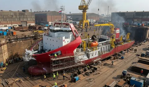
To make the concepts concrete, let's look closer at the hull erection phase of a 90-meter OPV.
Constraints and Assumptions:
- Drydock available from Week 1.
- The yard has a single 300-ton Gantry crane. Limit: Max wind speed 14 m/s.
- Target: Hull erection ready for main engine installation (Launch-ready) by Week 28.
Sample Week-by-Week Sequence (Crane-Levelled):
- Weeks 1-6: A01 Keel Block (under the Main Engine) is fabricated in the panel and assembly hall. Pipes are installed inside as part of advanced outfitting.
- Week 7 (Days 1-2): Block A01 is lowered into the drydock (Start of Critical Path).
- Week 7 (Days 4-5): Block A02 is lowered next to/behind A01. (A 3-day lag is included for position control and welding preparation of A01).
- Weeks 8-12: Midship ring blocks are closed sequentially. The gantry crane is fully booked every day during this period.
- Week 14: The engine room steel structure is 80% complete; milling of the main engine foundations begins.
During this process, the forward blocks (C01-C03) may appear to have ample float logically (pure logic), but when subjected to the crane usage plan (resource levelling), their float drops dramatically. Since waiting costs in the drydock are high, crane shifts might need to be doubled.
Modern Planning Software and Digital Practices
Traditional Excel spreadsheets are not adequate for managing hull block sequencing once a project reaches real scale.
- Enterprise Project Management (EPM) Tools: Oracle Primavera P6 or Microsoft Project are essential for the master schedule and CPM infrastructure.
- 4D Planning (Digital Twin): Using software like Navisworks, Synchro, or specialized shipbuilding tools (e.g., AVEVA or CADMATIC eShare), the 3D CAD model is linked with the Primavera schedule. This allows the block erection sequence to be "played" on-screen over a timeline, identifying crane clashes and access issues virtually.
- ERP Integration: Level 5 work packages (steel cutting, welding) at the shop floor level are transferred to ERP systems like SAP or IFS for hourly man-hour tracking.
Conclusion
Hull block construction sequencing and critical path management are not academic exercises on paper. They are the primary mechanisms by which a shipyard transforms a contracted delivery date into a coordinated sequence of physical work that hundreds of workers on the shop floor execute every day.
When done well, it reveals the true drivers of the schedule, protects bottleneck resources (cranes, drydocks, labor), and provides early warnings to project management when recovery plans are needed. When done poorly, it only creates a false sense of control for upper management, while the real problems remain hidden until weeks before the delivery date.
The methods detailed in this article, product-oriented hierarchy (PWBS), rigorous precedence logic, realistic duration estimates, resource-constrained float analysis, and EVM-based progress measurement, are widely used across commercial and naval shipyards, though the exact hierarchy levels, naming conventions and tooling vary by yard. Applied well, they're what separates a planner who produces an accurate calendar of dates from one who builds the operational logic the shipyard actually runs on.